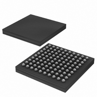
DS2155G Maxim Integrated Products, DS2155G Datasheet - Page 6

DS2155G
Manufacturer Part Number
DS2155G
Description
IC TXRX T1/E1/J1 1-CHIP 100CSBGA
Manufacturer
Maxim Integrated Products
Specifications of DS2155G
Function
Single-Chip Transceiver
Interface
E1, HDLC, J1, T1
Number Of Circuits
1
Voltage - Supply
3.14 V ~ 3.47 V
Current - Supply
75mA
Operating Temperature
0°C ~ 70°C
Mounting Type
Surface Mount
Package / Case
100-LFBGA
Includes
BERT Generator and Detector, CMI Coder and Decoder, HDLC Controller
Lead Free Status / RoHS Status
Contains lead / RoHS non-compliant
Power (watts)
-
Available stocks
Company
Part Number
Manufacturer
Quantity
Price
Part Number:
DS2155G+
Manufacturer:
MAXIM/美信
Quantity:
20 000
Company:
Part Number:
DS2155G+T&R
Manufacturer:
MAXIM
Quantity:
68
Company:
Part Number:
DS2155G+T&R
Manufacturer:
Maxim Integrated
Quantity:
10 000
Company:
Part Number:
DS2155G/T&R
Manufacturer:
Maxim Integrated
Quantity:
10 000
Part Number:
DS2155GN+
Manufacturer:
DALLAS
Quantity:
20 000
Company:
Part Number:
DS2155GNC2+T&R
Manufacturer:
MAXIM
Quantity:
14
18. WRITING TO THE HDLC TRANSMIT FIFO REQUIRES VERIFICATION
19. HDLC OPENING BYTE INDICATORS:
20. BERT DIRECTION BIT DOES NOT WORK
Description:
The potential exists for the data written into the HDLC transmit FIFO user ports (registers H1TF and
H2TF) not to be transferred into the HDLC transmit FIFOs.
Work Around:
Method 1–For messages less than 128 bytes in length:
1) Disable the transmitting of HDLC messages by setting all HxTCSx registers to 0.
2) For each byte to be written to the transmit FIFO:
3) Enable the transmitting of HDLC messages by setting the appropriate HxTCSx bits.
Method 2–Allows transmission of messages longer than 128 bytes in length:
1) Use the transmit multiframe-event interrupt to identify the location in time of a transmitted
2) Wait the appropriate amount of time from a multiframe boundary interrupt to ensure that the
3) Use the procedure from Step 2 in Method 1 for each byte of data until one multiframe worth of
4) Repeat Steps 2 and 3 until the message is completed and can be terminated with an end of
Method 3–Hardware mode, also allows transmission of long messages:
1) Use the rising edge of the 8XCLK pin to synchronize writing to the HDLC HxTF registers. The
Description:
Under certain conditions, the HDLC opening byte indicators (H1OBT and H2OBT) in the INFO4
register may not work correctly.
Work Around:
Poll the corresponding receive packet start (RPS) bit in the H1TTBBS and H2TTBBS registers.
Description:
Setting the BERT Direction bit (BIC.1) does not correctly map the BERT into the system side of the
device.
Work Around:
Do not use this bit. There is no known work around for this issue.
Retrieve the value of the transmit bytes available in the H1TFBA or H2TFBA register and store it.
Write the byte of HDLC data into the H1TF or H2TF register.
Compare the current value of H1TFBA or H2TFBA to the stored value.
If the current value has not been decremented by one, re-write byte of data into H1TF or H2TF.
multiframe boundary.
following write operation does not occur within a timeslot used to transmit HDLC data.
HDLC data has been loaded into the transmit HDLC FIFO.
message.
write operation must be completed prior to the falling edge of 8XCLK.
6 of 7
DS2155 ERRATA SHEET


