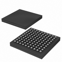
DS2155G Maxim Integrated Products, DS2155G Datasheet - Page 3

DS2155G
Manufacturer Part Number
DS2155G
Description
IC TXRX T1/E1/J1 1-CHIP 100CSBGA
Manufacturer
Maxim Integrated Products
Specifications of DS2155G
Function
Single-Chip Transceiver
Interface
E1, HDLC, J1, T1
Number Of Circuits
1
Voltage - Supply
3.14 V ~ 3.47 V
Current - Supply
75mA
Operating Temperature
0°C ~ 70°C
Mounting Type
Surface Mount
Package / Case
100-LFBGA
Includes
BERT Generator and Detector, CMI Coder and Decoder, HDLC Controller
Lead Free Status / RoHS Status
Contains lead / RoHS non-compliant
Power (watts)
-
Available stocks
Company
Part Number
Manufacturer
Quantity
Price
Part Number:
DS2155G+
Manufacturer:
MAXIM/美信
Quantity:
20 000
Company:
Part Number:
DS2155G+T&R
Manufacturer:
MAXIM
Quantity:
68
Company:
Part Number:
DS2155G+T&R
Manufacturer:
Maxim Integrated
Quantity:
10 000
Company:
Part Number:
DS2155G/T&R
Manufacturer:
Maxim Integrated
Quantity:
10 000
Part Number:
DS2155GN+
Manufacturer:
DALLAS
Quantity:
20 000
Company:
Part Number:
DS2155GNC2+T&R
Manufacturer:
MAXIM
Quantity:
14
5. RECEIVE FRACTIONAL SUPPORT
6. HDLC FIFO
7. HDLC TIMING
Description:
The receive fractional support (alternate function of the RCHCLK pin) does not operate as described
in the data sheet. Receive data at the RSER pin is updated on the rising edge of RCLK. In fractional
support mode the RCHCLK pin should output a clock (gated version of RCLK) during a selected
channel or channels. The falling edge of this clock could be used by the backplane to sample data
output on the RSER pin. However, RCHCLK is delayed one half clock in this rev of the DS2155.
Work Around:
As an alternate method, the backplane can use the rising edge RCHCLK to sample data output form
RSER.
Description:
HDLC FIFOs cannot be read from or written to at full bus speed. Writing at a speed >4.7MHz can
cause data corruption in the FIFOs.
Work Around:
Keep the HDLC read and write speed below 4.7MHz.
Description:
While in framer loopback mode, received HDLC data can be corrupted when MCLK and TCLK
rising edges are <30ns apart. When not in framer loopback mode, data can be corrupted if the edges
of RCLK and the internally generated 8XCLK occur simultaneously.
Work Around:
Separate the rising edges of MCLK and TCLK by more than 30ns when in framer loopback. When
not in framer loopback mode, placing the jitter attenuator in the receive path (LIC1 = 00h) phase-
locks the 8XCLK with RCLK and avoids data corruption.
RCLK
RCHCLK
RCHCLK
DATA SHEET
ACTUAL
SELECTED CHANNEL
3 of 7
DS2155 ERRATA SHEET


