DS2153Q-A7+T&R Maxim Integrated Products, DS2153Q-A7+T&R Datasheet - Page 15
DS2153Q-A7+T&R
Manufacturer Part Number
DS2153Q-A7+T&R
Description
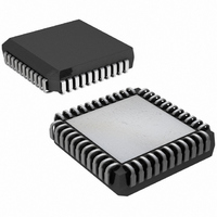
IC TXRX E1 1-CHIP 5V 44-PLCC
Manufacturer
Maxim Integrated Products
Datasheet
1.DS2153Q-A7TR.pdf
(60 pages)
Specifications of DS2153Q-A7+T&R
Function
Single-Chip Transceiver
Interface
E1
Number Of Circuits
1
Voltage - Supply
4.75 V ~ 5.25 V
Current - Supply
65mA
Operating Temperature
0°C ~ 70°C
Mounting Type
Surface Mount
Package / Case
*
Lead Free Status / RoHS Status
Lead free / RoHS Compliant
Power (watts)
-


CCR2: COMMON CONTROL REGISTER 2 (Address = 1A Hex)
(MSB)
ECUS
SYMBOL
LOTCMC
VCRFS
RSERC
ECUS
AAIS
ARA
RLB
LLB
VCRFS
POSITION
CCR2.7
CCR2.6
CCR2.5
CCR2.4
CCR2.3
CCR2.2
CCR2.1
CCR2.0
AAIS
NAME AND DESCRIPTION
Error Counter Update Select.
0 = update error counters once a second
1 = update error counters every 62.5ms (500 frames)
VCR Function Select.
0 = count Bipolar Violations (BPVs)
1 = count Code Violations (CVs)
Automatic AIS Generation.
0 = disabled
1 = enabled
Automatic Remote Alarm Generation.
0 = disabled
1 = enabled
RSER Control.
0 = allow RSER to output data as received under all conditions
1 = force RSER to 1 under loss of frame alignment conditions
Loss of Transmit Clock Mux Control. Determines whether the
transmit side formatter should switch to the ever present RCLK
if the TCLK should fail to transition (see
0 = do not switch to RCLK if TCLK stops
1 = switch to RCLK if TCLK stops
Remote Loopback.
0 = loopback disabled
1 = loopback enabled
Local Loopback.
0 = loopback disabled
1 = loopback enabled
ARA
15 of 60
RSERC
LOTCMC
Figure
RLB
1-1).
(LSB)
LLB
Related parts for DS2153Q-A7+T&R
Image
Part Number
Description
Manufacturer
Datasheet
Request
R

Part Number:
Description:
Manufacturer:
Maxim Integrated Products
Datasheet:

Part Number:
Description:
IC TXRX E1 1-CHIP 5V 44-PLCC
Manufacturer:
Maxim Integrated Products
Part Number:
Description:
IC TXRX E1 1-CHIP 5V 44-PLCC
Manufacturer:
Maxim Integrated Products
Part Number:
Description:
MAX7528KCWPMaxim Integrated Products [CMOS Dual 8-Bit Buffered Multiplying DACs]
Manufacturer:
Maxim Integrated Products
Datasheet:
Part Number:
Description:
Single +5V, fully integrated, 1.25Gbps laser diode driver.
Manufacturer:
Maxim Integrated Products
Datasheet:
Part Number:
Description:
Single +5V, fully integrated, 155Mbps laser diode driver.
Manufacturer:
Maxim Integrated Products
Datasheet:
Part Number:
Description:
VRD11/VRD10, K8 Rev F 2/3/4-Phase PWM Controllers with Integrated Dual MOSFET Drivers
Manufacturer:
Maxim Integrated Products
Datasheet:
Part Number:
Description:
Highly Integrated Level 2 SMBus Battery Chargers
Manufacturer:
Maxim Integrated Products
Datasheet:
Part Number:
Description:
Current Monitor and Accumulator with Integrated Sense Resistor; ; Temperature Range: -40°C to +85°C
Manufacturer:
Maxim Integrated Products
Part Number:
Description:
TSSOP 14/A°/RS-485 Transceivers with Integrated 100O/120O Termination Resis
Manufacturer:
Maxim Integrated Products
Part Number:
Description:
TSSOP 14/A°/RS-485 Transceivers with Integrated 100O/120O Termination Resis
Manufacturer:
Maxim Integrated Products
Part Number:
Description:
QFN 16/A°/AC-DC and DC-DC Peak-Current-Mode Converters with Integrated Step
Manufacturer:
Maxim Integrated Products
Part Number:
Description:
TDFN/A/65V, 1A, 600KHZ, SYNCHRONOUS STEP-DOWN REGULATOR WITH INTEGRATED SWI
Manufacturer:
Maxim Integrated Products
Part Number:
Description:
Integrated Temperature Controller f
Manufacturer:
Maxim Integrated Products
Part Number:
Description:
SOT23-6/I°/45MHz to 650MHz, Integrated IF VCOs with Differential Output
Manufacturer:
Maxim Integrated Products