DS2180AQ+T&R Maxim Integrated Products, DS2180AQ+T&R Datasheet - Page 8
DS2180AQ+T&R
Manufacturer Part Number
DS2180AQ+T&R
Description
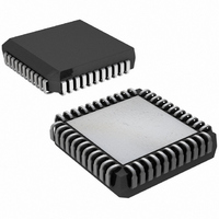
IC TRANSCEIVER T1 44-PLCC
Manufacturer
Maxim Integrated Products
Datasheet
1.DS2180A.pdf
(35 pages)
Specifications of DS2180AQ+T&R
Function
Transceiver
Interface
T1
Number Of Circuits
1
Voltage - Supply
4.5 V ~ 5.5 V
Current - Supply
3mA
Operating Temperature
0°C ~ 70°C
Mounting Type
Surface Mount
Package / Case
44-LCC, 44-PLCC
Includes
Alarm Generation and Detection, B7 Stuffing Mode, B8ZS Mode, Error Detection and Counter, "Hardware" Mode, Transparent Mode
Lead Free Status / RoHS Status
Lead free / RoHS Compliant
Power (watts)
-


B8ZS
The DS2180A supports existing and emerging zero suppression formats. Selection of B8ZS coding
maintains system 1’s density requirements without disturbing data integrity as required in emerging clear
channel applications. B8ZS coding replaces eight consecutive outgoing 0's with a B8ZS code word. Any
received B8ZS code word is replaced with all 0’s. B8ZS and bit 7 stuffing modes should not be enabled
simultaneously. Enabling both results in LOS.
TCR: TRANSMIT CONTROL REGISTER Figure 5
(MSB)
TRANSMIT BLUE ALARM
The blue alarm (also known as the AIS, Alarm Indication Signal) is an unframed, all 1’s sequence
enabled by asserting TCR.1. Blue alarm overrides all other transmit data patterns and is disabled by
clearing TCR.1. Use of the TIR registers allows a framed, all 1’s alarm transmission if required by the
network.
TRANSMIT YELLOW ALARM
In 193E framing, a yellow alarm is a repeating pattern set of FF(Hex) and 00 (Hex) on the 4 kHz facility
data link (FDL). In 193S framing the yellow alarm format is dependent on the state of bit CCR.3. In all
modes, yellow alarm is enabled by asserting TCR.0 and disabled by clearing TCR.0.
SYMBOL
ODF
TYEL
RBSE
193SI
TFPT
ODF
TBL
TCP
TIS
TFPT
POSITION
TCR.7
TCR.6
TCR.5
TCR.4
TCR.3
TCR.2
TCR.1
TCR.0
TCP
NAME AND DESCRIPTION
Output Data Format.
0 = Bipolar data at TPOS and TNEG.
1 = NRZ data at TPOS; TNEG=0.
Transmit Framing Pass-through.
0 = FT/FPS sourced internally.
1 = FT/FPS sampled at TSER during F-bit time.
Transmit CRC Pass-through.
0 = Transmit CRC code internally generated.
1 = TSER sampled at CRC F-bit time for external CRC insertion.
Robbed Bit Signaling Enable.
1 = Signaling inserted in all channels during signaling frames.
0 = No signaling inserted. (The TTR registers allow the user to
disable signaling insertion on selected DS0 channels.)
Transmit Idle Code Select. Determines idle code format to be
inserted into channels marked by the TIR registers.
0 = Insert 7F (Hex) into marked channels.
1 = Insert FF (Hex) into marked channels.
193S S-bit Insertion. Determines source of transmitted S-bit.
0 = Internal S-bit generator.
1 = External (sampled at TLINK input).
Transmit Blue Alarm.
0 = Disabled.
1 = Enabled.
TYEL TCR.0 Transmit Yellow Alarm.
0 = Disabled.
1 = Enabled.
RBSE
8 of 35
TIS
193SI
TBL
(LSB)
TYEL
DS2180A
Related parts for DS2180AQ+T&R
Image
Part Number
Description
Manufacturer
Datasheet
Request
R

Part Number:
Description:
IC TRANSCEIVER T1 44-PLCC
Manufacturer:
Maxim Integrated Products
Datasheet:

Part Number:
Description:
IC TRANSCEIVER T1 44-PLCC
Manufacturer:
Maxim Integrated Products
Datasheet:
Part Number:
Description:
IC TRANSCEIVER T1 44-PLCC
Manufacturer:
Maxim Integrated Products
Datasheet:

Part Number:
Description:
IC TRANSCEIVER T1 40-DIP
Manufacturer:
Maxim Integrated Products
Datasheet:
Part Number:
Description:
IC TRANSCEIVER T1 40-DIP
Manufacturer:
Maxim Integrated Products
Datasheet:

Part Number:
Description:
MAX7528KCWPMaxim Integrated Products [CMOS Dual 8-Bit Buffered Multiplying DACs]
Manufacturer:
Maxim Integrated Products
Datasheet:
Part Number:
Description:
Single +5V, fully integrated, 1.25Gbps laser diode driver.
Manufacturer:
Maxim Integrated Products
Datasheet:
Part Number:
Description:
Single +5V, fully integrated, 155Mbps laser diode driver.
Manufacturer:
Maxim Integrated Products
Datasheet:
Part Number:
Description:
VRD11/VRD10, K8 Rev F 2/3/4-Phase PWM Controllers with Integrated Dual MOSFET Drivers
Manufacturer:
Maxim Integrated Products
Datasheet:
Part Number:
Description:
Highly Integrated Level 2 SMBus Battery Chargers
Manufacturer:
Maxim Integrated Products
Datasheet:
Part Number:
Description:
Current Monitor and Accumulator with Integrated Sense Resistor; ; Temperature Range: -40°C to +85°C
Manufacturer:
Maxim Integrated Products
Part Number:
Description:
TSSOP 14/A�/RS-485 Transceivers with Integrated 100O/120O Termination Resis
Manufacturer:
Maxim Integrated Products
Part Number:
Description:
TSSOP 14/A�/RS-485 Transceivers with Integrated 100O/120O Termination Resis
Manufacturer:
Maxim Integrated Products
Part Number:
Description:
QFN 16/A�/AC-DC and DC-DC Peak-Current-Mode Converters with Integrated Step
Manufacturer:
Maxim Integrated Products
Part Number:
Description:
TDFN/A/65V, 1A, 600KHZ, SYNCHRONOUS STEP-DOWN REGULATOR WITH INTEGRATED SWI
Manufacturer:
Maxim Integrated Products