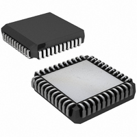
DS2180AQ+T&R Maxim Integrated Products, DS2180AQ+T&R Datasheet - Page 7

DS2180AQ+T&R
Manufacturer Part Number
DS2180AQ+T&R
Description
IC TRANSCEIVER T1 44-PLCC
Manufacturer
Maxim Integrated Products
Datasheet
1.DS2180A.pdf
(35 pages)
Specifications of DS2180AQ+T&R
Function
Transceiver
Interface
T1
Number Of Circuits
1
Voltage - Supply
4.5 V ~ 5.5 V
Current - Supply
3mA
Operating Temperature
0°C ~ 70°C
Mounting Type
Surface Mount
Package / Case
44-LCC, 44-PLCC
Includes
Alarm Generation and Detection, B7 Stuffing Mode, B8ZS Mode, Error Detection and Counter, "Hardware" Mode, Transparent Mode
Lead Free Status / RoHS Status
Lead free / RoHS Compliant
Power (watts)
-
ACB: ADDRESS COMMAND BYTE Figure 4
(MSB)
LOOPBACK (Refer to Figure 4)
Enabling loopback will typically induce an out-of-frame (OOF) condition. If appropriate bits are set in
the receive control register, the receiver will resync to the looped transmit frame alignment. During the
looped condition, the transmit outputs (TPOS, TNEG) will transmit unframed all 1's. All operating modes
(B8ZS, alarm, signaling, etc.) except for blue alarm transmission are available in loopback.
BIT SEVEN STUFFING
Existing systems meet 1's density requirements by forcing bit 7 of all zero channels to 1. Bit 7 stuffing is
globally enabled by asserting bit CCR.1 and may be disabled on an individual channel basis by setting
appropriate bits in TTR1–TTR3. Bit 7 stuffing and B8ZS modes should not be enabled simultaneously.
Enabling both results in LOS.
SYMBOL
EYELMD
SYELMD
FRSR2
LPBK
B8ZS
FM
-
B7
-
FRSR2
POSITION
CCR.6
CCR.7
CCR.5
CCR.4
CCR.3
CCR.2
CCR.1
CCR.0
EYELMD
NAME AND DESCRIPTION
Reserved, must be 0 for proper operation.
Function of REC Status Register 2.
0 = Detected B8ZS code words reported at RSR.2.
1 = COFA (Change-of-Frame Alignment) reported at RSR.2 when
last resync resulted in change of frame or multiframe alignment.
193E Yellow Mode Select.
0 = Yellow alarm is a repeating pattern set of 00 hex and FF hex.
1 = Yellow alarm is a 0 in the bit 2 position of all channels.
Frame Mode Select.
0 = D4 (193S, 12 frames/superframe).
1 = Extended (193E, 24 frames/superframe).
193S Yellow Mode Select. Determines yellow alarm type to be
transmitted and detected while in 193S framing. If set, yellow
alarms are a 1 in the S-bit position of frame 12; if cleared, yellow
alarm is a 0 in bit 2 of all channels. Does not affect 193E yellow
alarm operation.
Bipolar eight zero substitution.
0 = No B8ZS.
1 = B8ZS enabled.
(Note: This bit must be set to 0 when CCR.1=1)
Bit seven zero suppression. If CCR.1=1, channels with an all zero
content will be transmitted with bit 7 forced to 1. If CCR.1=0, no
bit 7 stuffing occurs.
(Note: This bit must be set to 0 when CCR.2=1)
Loopback. When set, the device internally loops output transmit
data into the incoming receive data buffers and TCLK is internally
substituted for RCLK.
FM
7 of 35
SYELMD
B8ZS
B7
(LSB)
LPBK
DS2180A


