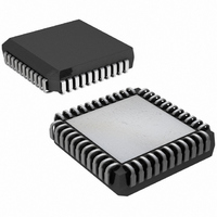
DS2180AQ+T&R Maxim Integrated Products, DS2180AQ+T&R Datasheet - Page 14

DS2180AQ+T&R
Manufacturer Part Number
DS2180AQ+T&R
Description
IC TRANSCEIVER T1 44-PLCC
Manufacturer
Maxim Integrated Products
Datasheet
1.DS2180A.pdf
(35 pages)
Specifications of DS2180AQ+T&R
Function
Transceiver
Interface
T1
Number Of Circuits
1
Voltage - Supply
4.5 V ~ 5.5 V
Current - Supply
3mA
Operating Temperature
0°C ~ 70°C
Mounting Type
Surface Mount
Package / Case
44-LCC, 44-PLCC
Includes
Alarm Generation and Detection, B7 Stuffing Mode, B8ZS Mode, Error Detection and Counter, "Hardware" Mode, Transparent Mode
Lead Free Status / RoHS Status
Lead free / RoHS Compliant
Power (watts)
-
RECEIVE CONTROL REGISTER Figure 12
(MSB)
RECEIVE CODE INSERTION
Incoming receive channels can be replaced with idle (7F Hex) or digital milliwatt ( -LAW format) codes.
The receive mark registers indicate which channels are inserted. When set, bit RCR.5 serves as a
“global” enable for marked channels and bit RCR.4 selects inserted code format: 0 = idle code, 1 = digital
milliwatt.
RECEIVE SYNCHRONIZER
Bits RCR.0 through RCR.3 allow the user to control operational characteristics of the synchronizer. Sync
algorithm, candidate qualify testing, auto resync, and command resync modes may be altered at any time
in response to changing span conditions.
SYMBOL
RESYNC
SYNCC
SYNCT
SYNCE
ARC
ARC
OOF
RCS
RCI
OOF
POSITION
RCR.3
RCR.1
RCR.7
RCR.6
RCR.5
RCR.4
RCR.2
RCR.0
RCI
NAME AND DESCRIPTION
Auto Resync Criteria.
0 = Resync on OOF or RCL event.
1 = Resync on OOF only.
Out-of-frame (OOF) Condition Detection.
0 = 2 of 4 framing bits in error.
1 = 2 of 5 framing bits in error.
Receive Code Insert. When set, the receive code selected by
RCR.4 is inserted into channels marked by RMR registers. If clear,
no code is inserted.
Receive Code Select.
0 = Idle code (7F Hex).
1 = Digital milliwatt.
Sync Criteria. Determines the type of algorithm utilized by the
receive synchronizer and differs for each frame mode.
193S Framing (CCR.4=0).
0 = Synchronize to frame boundaries using F
for multiframe by using F
1 = Cross couple F
193E Framing (CCR.4=1).
0 = Normal sync (utilizes FPS only).
1 = Validate new alignment with CRC before declaring sync.
Sync Time. If set, 24 consecutive F-bits of the framing pattern
must be qualified before sync is declared. If clear, 10 bits are
qualified.
Sync Enable. If clear, the transceiver will automatically begin a
resync if two of the previous four or five framing bits were in error
or if carrier loss is detected. If set, no auto resync occurs.
Resync. When toggled low to high, the transceiver will initiate
resync immediately. The bit must be cleared, then set again for
subsequent resyncs.
RCS
14 of 35
SYNCC
T
and F
S
S
.
patterns in sync algorithm.
SYNCT
SYNCE
T
pattern, then search
RESYNC
(LSB)
DS2180A


