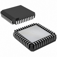
DS2151QB+ Maxim Integrated Products, DS2151QB+ Datasheet - Page 23

DS2151QB+
Manufacturer Part Number
DS2151QB+
Description
IC TXRX T1 1-CHIP 5V LP 44-PLCC
Manufacturer
Maxim Integrated Products
Datasheet
1.DS2151QB.pdf
(60 pages)
Specifications of DS2151QB+
Function
Single-Chip Transceiver
Interface
T1
Number Of Circuits
1
Voltage - Supply
4.75 V ~ 5.25 V
Current - Supply
65mA
Operating Temperature
0°C ~ 70°C
Mounting Type
Surface Mount
Package / Case
44-LCC, 44-PLCC
Includes
Alarm Detector and Generator, CSU Loop Codes Generator and Detector, DSX-1 and CSU Line Build-Outs Generator
Lead Free Status / RoHS Status
Lead free / RoHS Compliant
Power (watts)
-
Table 5-2. Alarm Set and Clear Criteria
Note: The definition of Blue Alarm (or Alarm Indication Signal) is an unframed all-ones signal. Blue alarm detectors should
be able to operate properly in the presence of a 10-3 error rate and they should not falsely trigger on a framed all-ones signal.
The blue alarm criteria in the DS2151Q has been set to achieve this performance. It is recommended that the RBL bit be
qualified with the RLOS status bit in detecting a blue alarm.
5.1
Bits SR1.7 and SR1.6 will indicate when either the standard Loop Up or Loop Down codes are being
received by the DS2151Q. When a Loop Up code has been received for 5 seconds, the CPE is expected to
loop the recovered data (without correcting BPVs) back to the source. The Loop Down code indicates
that the loopback should be discontinued. See the AT&T publication TR 62411 for more details. The
DS2151Q will detect the Loop Up/Down codes in both framed and unframed circumstances with bit error
rates as high as 10**-2. The loop code detector has a nominal integration period of 48ms. Hence, after
about 48ms of receiving either code, the proper status bit will be set to a 1. After this initial indication, it
is recommended that the software poll the DS2151Q every 100ms to 500ms until 5 seconds have elapsed
to insure that the code is continuously present. Once 5 seconds have passed, the DS2151Q should be
taken into or out of loopback via the Remote Loopback (RLB) bit in CCR1.
Blue Alarm (AIS) (see note below)
Yellow Alarm
1. D4 bit 2 mode (RCR2.2=0)
2. D4 12
3. ESF Mode
Red Alarm (RCL) (this alarm is
also referred to as Loss of Signal)
this mode is also referred to as
the “Japanese Yellow Alarm”)
Loop Up/Down Code Detection
th
F-bit mode (RCR2.2=1;
ALARM
When over a 3ms window, five or
less 0s are received
When bit 2 of 256 consecutive
channels is set to 0 for at least 254
occurrences
When the 12
1 for two consecutive occurrences
When 16 consecutive patterns of
00FF hex appear in the FDL
When 192 consecutive 0s are
received
SET CRITERIA
th
23 of 60
framing bit is set to
When over a 3ms window, six or
more 0s are received
When bit 2 of 256 consecutive
channels is set to 0 for less than 254
occurrences
When the 12
for two consecutive occurrences
When 14 or less patterns of 00FF
hex out of 16 possible appear in the
FDL
When 14 or more 1s out of 112
possible bit positions are received
starting with the first 1 received
CLEAR CRITERIA
th
framing bit is set to 0


