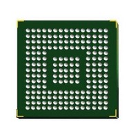
STM32F417IGH6 STMicroelectronics, STM32F417IGH6 Datasheet - Page 64

STM32F417IGH6
Manufacturer Part Number
STM32F417IGH6
Description
Microcontrollers (MCU) ARM M4 1024 FLASH 168 Mhz 192kB SRAM
Manufacturer
STMicroelectronics
Specifications of STM32F417IGH6
Core
ARM Cortex M4
Processor Series
STM32F4
Data Bus Width
32 bit
Maximum Clock Frequency
168 MHz
Program Memory Size
1024 KB
Data Ram Size
192 KB
On-chip Adc
Yes
Number Of Programmable I/os
140
Number Of Timers
10
Operating Supply Voltage
1.7 V to 3.6 V
Package / Case
UFBGA-176
Mounting Style
SMD/SMT
A/d Bit Size
12 bit
A/d Channels Available
24
Interface Type
CAN, I2C, I2S, SPI, UART
Program Memory Type
Flash
Lead Free Status / Rohs Status
Details
Available stocks
Company
Part Number
Manufacturer
Quantity
Price
Company:
Part Number:
STM32F417IGH6
Manufacturer:
STMicroelectronics
Quantity:
480
Electrical characteristics
5.3.6
64/156
Table 15.
1. TBD stands for “to be defined”.
2. The product behavior is guaranteed by design down to the minimum V
3. Guaranteed by design, not tested in production.
4. The reset temporization is measured from the power-on (POR reset or wakeup from V
Supply current characteristics
The current consumption is a function of several parameters and factors such as the
operating voltage, ambient temperature, I/O pin loading, device software configuration,
operating frequencies, I/O pin switching rate, program location in memory and executed
binary code.
The current consumption is measured as described in
measurement
All Run mode current consumption measurements given in this section are performed using
a CoreMark-compliant code.
Typical and maximum current consumption
The MCU is placed under the following conditions:
●
●
●
T
RSTTEMPO
V
when first instruction is read by the user application code.
E
Symbol
BORhyst
I
At startup, all I/O pins are configured as analog inputs by firmware.
All peripherals are disabled except if it is explicitly mentioned.
The
30 MHz, 1 wait state from 30 to 60 MHz, 2 wait states from 60 to 90 MHz, 3 wait states
V
V
V
RUSH
RUSH
BOR1
BOR2
BOR3
Flash
(3)
(3)
(3)
(3)(4)
Embedded reset and power control block characteristics
scheme.
memory access time is adjusted to f
Brownout level 1
threshold
Brownout level 2
threshold
Brownout level 3
threshold
BOR hysteresis
Reset temporization
InRush current on
voltage regulator
power-on (POR or
wakeup from Standby)
InRush energy on
voltage regulator
power-on (POR or
wakeup from Standby)
Parameter
Doc ID 022063 Rev 1
Falling edge
Rising edge
Falling edge
Rising edge
Falling edge
Rising edge
V
I
RUSH
DD
= 1.8 V, T
= 171 mA for 31 µs
Conditions
HCLK
A
= 105 °C,
Figure 19: Current consumption
frequency (0 wait state from 0 to
POR/PDR
STM32F415xx, STM32F417xx
2.13
2.23
2.44
2.53
2.75
2.85
Min
0.5
value.
-
-
-
BAT
2.19
2.29
2.50
2.59
2.83
2.92
Typ
100
160
1.5
(1)
-
) to the instant
(continued)
Max
2.24
2.33
2.56
2.63
2.88
2.97
200
3.0
5.4
-
Unit
mV
mA
ms
µC
V
V
V
V
V


