ES-FL-2A BANNER ENGINEERING, ES-FL-2A Datasheet - Page 4
ES-FL-2A
Manufacturer Part Number
ES-FL-2A
Description
20H6269
Manufacturer
BANNER ENGINEERING
Datasheet
1.ES-FL-2A.pdf
(8 pages)
Specifications of ES-FL-2A
Coil Voltage Vac Nom
24V
Coil Voltage Vdc Nom
24V
Contact Current Max
4A
Contact Voltage Ac Nom
250V
Contact Voltage Dc Nom
250V
Contact Configuration
DPDT-NC
No. Of Poles
2


E-Stop Safety Relay
As shown in Figure 2 or 3, the emergency stop switch must provide two contacts which are closed when the switch is in the
“armed” position. Once activated, the emergency stop switch must open both contacts. The switch may be returned to the closed-
contact position only by a deliberate action such as twisting, pulling, unlocking, etc. Additionally, ANSI B11 standards specify the
following switch (i. e. “stop control”) requirements:
The model ES-FL-2A safety relay must be installed inside an enclosure. It is not designed for exposed wiring. It is the user’s
responsibility to house the safety relay in an enclosure with NEMA 3 (IEC IP54) rating, or better.
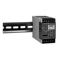
Dimensions of the safety relay are shown in the diagram on page 8. The safety relay mounts directly to standard 35mm DIN rail.
It is not possible to give exact wiring instructions for a device such as the model ES-FL-2A emergency stop monitoring
safety relay which interfaces to a multitude of machine control configurations. The following guidelines are general in
nature.
Model ES-FL-2A has no delay function. The output relay contacts open (and the monitoring contact closes) within 25
milliseconds from the time that either emergency stop switch contact opens. This classifies the ES-FL-2A as a functional
“Category 0” emergency stop control as defined by NFPA 79 (National Fire Protection Association Standard for Industrial
Machinery) and EN418 (European Standard: “Safety of Machinery, Emergency Stop Equipment, Functional Aspects –
Principles of Design”).
Connect the two poles of the emergency stop switch as shown in Figure 2. The switch in Figure 2 is shown in its “armed” position
with both contacts closed. Multiple emergency stop switches connected to one safety relay must use a series connection (see
Figure 3 and the warning, below).
page
SECTION 2 – Emergency Stop Switch Requirements
SECTION 3 – Mechanical Installation
SECTION 4 – Electrical Installation
SECTION 4.1 – Connection of Emergency Stop Switch
monitoring ability of the safety relay, and creates an unsafe condition which could result in serious injury or death.
4
!
“A typical stop control may be a button, cable, trip bar, foot control, or other sensing means. The
“An emergency stop control shall be provided for each operator control station or position and
stop control should be colored red and should be clearly labeled.”
shall be readily distinguishable from all other operating controls.”
CAUTION
being controlled before making any wire connections.
Electrical installation and wiring must be made by qualified personnel and must comply with the NEC
(National Electrical Code), EN60204-1 and -2, and all applicable local standards and codes.
WARNING
contacts of the corresponding pole of each switch must be connected together in series. This series combination
is then wired to the respective safety relay input (i.e. to either S13 and S14 or S23 and S24). Never connect the
contacts of multiple emergency stop switches in parallel to the ES-FL-2A safety relay inputs. Parallel
connection of two or more emergency stop switches to one ES-FL-2A safety relay defeats the switch contact
Always disconnect power from the ES-FL-2A safety relay and all power from the machine
Whenever two or more emergency stop switches are connected to the same ES-FL-2A safety relay,
Related parts for ES-FL-2A
Image
Part Number
Description
Manufacturer
Datasheet
Request
R

Part Number:
Description:
98H7885
Manufacturer:
BANNER ENGINEERING
Datasheet:

Part Number:
Description:
Photoelectric Sensor
Manufacturer:
BANNER ENGINEERING
Datasheet:

Part Number:
Description:
Photoelectric Sensor
Manufacturer:
BANNER ENGINEERING
Datasheet:

Part Number:
Description:
LEDIR70XD4-XM-81039 MAX INTENS STROBE ONLY NO BANNER MARKS
Manufacturer:
BANNER ENGINEERING
Part Number:
Description:
M18SP6DL-72225 LABELED MOELLER NO BANNER MARKINGS BULK PACK
Manufacturer:
BANNER ENGINEERING
Part Number:
Description:
M18SP6DLQ-72226 LABLED MOELLER NO BANNER MARKINGS BULK PACK
Manufacturer:
BANNER ENGINEERING
Part Number:
Description:
M18SP6L-72223 LABELED MOELLER NO BANNER MARKINGS BULK PACK
Manufacturer:
BANNER ENGINEERING
Part Number:
Description:
M18SP6LQ-72224 LABELED MOELLER NO BANNER MARKINGS BULK PACK
Manufacturer:
BANNER ENGINEERING
Part Number:
Description:
Sensor, E-stop Module, output 6A,
Manufacturer:
BANNER ENGINEERING
Datasheet:
Part Number:
Description:
Photoelectric Sensor
Manufacturer:
BANNER ENGINEERING
Datasheet:

Part Number:
Description:
Programmable Indicator Light
Manufacturer:
BANNER ENGINEERING
Datasheet:
Part Number:
Description:
INDICATOR LED PANEL 50MM GRN/RED/YEL 30V
Manufacturer:
BANNER ENGINEERING
Datasheet: