ES-FL-2A BANNER ENGINEERING, ES-FL-2A Datasheet
ES-FL-2A
Specifications of ES-FL-2A


Related parts for ES-FL-2A


ES-FL-2A Summary of contents
Page 1
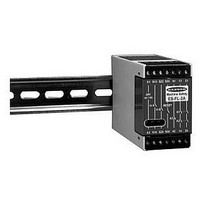
... Design complies with standards UL991, EN418, and EN954-1(Safety Category 4) • UL approved as Category NISD Emergency Stop Device • For use in functional stop category 0 applications per NFPA 79 and EN418 Printed in USA Emergency Stop Monitoring Safety Relay Model ES-FL-2A Emergency Stop Devices R 29YL ...
Page 2
... Banner Engineering Corp. has made every effort to provide complete application, installation, operation, and maintenance instructions. In addition, any questions regarding the use or installation of Banner Emergency Stop Monitoring Safety Relay model ES-FL-2A should be directed to the factory applications department at the telephone numbers or address shown on back cover. ...
Page 3
... SECTION 1 – Product Description The purpose of safety relay model ES-FL- increase the control reliability of an emergency stop circuit. The ANSI B11.19 standard states: “Control reliability of electrical, electronic, or pneumatic systems frequently consists of multiple, independent parallel or series circuitry or components so arranged that any single failure would not significantly affect the stopping performance of the system or the machine tool ...
Page 4
... SECTION 3 – Mechanical Installation The model ES-FL-2A safety relay must be installed inside an enclosure not designed for exposed wiring the user’s responsibility to house the safety relay in an enclosure with NEMA 3 (IEC IP54) rating, or better. ...
Page 5
... MSC2). NEVER install suppressors directly across the output contacts of ! the ES-FL-2A safety relay possible for suppressors to fail as a short circuit. If installed directly across the output contacts of the safety relay, a short-circuited suppressor will create an unsafe condition which could result in serious injury or death ...
Page 6
... The action of the auxiliary monitor contact, K3, inversely “follows” the action of the output relays, K1 and K2 when power is applied to the ES-FL-2A safety relay. The contact open when the output contacts of K1 and K2 are closed, and vice versa. The K3 auxiliary monitor contact is a light-duty contact to be used only for control functions that are NOT safety-related. A typical use is to communicate the status of the safety relay output to a programmable logic controller (PLC) ...
Page 7
... Apply input power (only) to the ES-FL-2A safety relay at terminals A1 and A2. Verify that only the Input Power indicator (Figure 1) is on. If either of the other two indicators this point, disconnect the input power and check all wiring. Return to step 2 after the cause of the problem has been corrected. ...
Page 8
... Input Requirements Emergency stop switch must have two normally closed contacts each capable of switching 40 to 100mA @ 12 to 18V dc. Reset switch must have one normally open contact capable of switching 40 to 100mA @ 12 to 18V dc. Status Indicators 3 green LED indicators: Power ON K1 energized ...