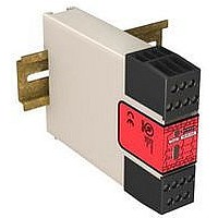
ES-FA-11AA BANNER ENGINEERING, ES-FA-11AA Datasheet - Page 11

ES-FA-11AA
Manufacturer Part Number
ES-FA-11AA
Description
98H7885
Manufacturer
BANNER ENGINEERING
Datasheet
1.ES-FA-11AA.pdf
(16 pages)
Specifications of ES-FA-11AA
Coil Voltage Vac Nom
24V
Coil Voltage Vdc Nom
24V
Contact Current Max
7A
Contact Voltage Ac Nom
250V
Contact Voltage Dc Nom
250V
No. Of Poles
2
Relay Mounting
DIN Rail
External Height
80mm
ES-FA-9AA / ES-FA-11AA E-Stop Safety Modules
1. Remove power from the machine control elements.
2. Ensure the safety device is in a STOP or "open-contact" state (e.g., actuate the E-stop switch to open its contacts).
3. Apply power to the Safety Module at terminals A1 and A2 (see Figures 4, 5, 6, and 7). Verify that only the Input
4. Reset or otherwise cause the safety device to reach an ON or "closed-contact" state (e.g., arm the E-stop switch
5. Automatic reset: Ch1 (K1) and Ch2 (K2) indicators should come ON, and the safety output contacts should
P/N 060606 rev. E
If arc suppressors are used, they MUST be installed as shown across the actuator coil of the master stop
control elements (MSC1 to MSC3). NEVER install suppressors directly across the output contacts of the
Safety Module. It is possible for suppressors to fail as a short circuit. If installed directly across the output contacts
of the Safety Module, a short-circuited suppressor will create an unsafe condition which could result in se-
rious injury or death.
Figure 6: Machine control circuit connections
Before performing the initial checkout procedure, make certain all power is disconnected from the machine
to be controlled.
Dangerous voltages may be present along the Safety Module wiring barriers whenever power to the machine
control elements is ON. Exercise extreme caution whenever machine control power is or may be present.
Always disconnect power to the machine control elements before opening the enclosure that houses the
Safety Module.
Power indicator (Figure 1) is ON. If either input channel 1 (K1) or input channel 2 (K2) indicators are ON at this
point, disconnect the input power and check all wiring. Return to step 2 after the cause of the problem has been
corrected.
to close its contacts).
close.
CAUTION . . . Disconnect Power Prior to Checkout
WARNING . . . Wiring of Arc Suppressors
Banner Engineering Corp. - Minneapolis, MN USA - www.bannerengineering.com
Initial Checkout Procedure
Tel: 763.544.3164
11


