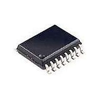
PCA9516APW NXP Semiconductors, PCA9516APW Datasheet - Page 5

PCA9516APW
Manufacturer Part Number
PCA9516APW
Description
I/O Expanders, Repeaters & Hubs I2C BUS HUB 5-CH
Manufacturer
NXP Semiconductors
Datasheet
1.PCA9516AD112.pdf
(19 pages)
Specifications of PCA9516APW
Logic Family
PCA
Number Of Lines (input / Output)
14 / 10
Propagation Delay Time
150 ns
Operating Supply Voltage
2.3 V to 3.6 V
Power Dissipation
300 mW
Operating Temperature Range
- 40 C to + 85 C
Package / Case
TSSOP-16
Logic Type
I2C Hub
Mounting Style
SMD/SMT
Number Of Input Lines
14
Number Of Output Lines
10
Lead Free Status / Rohs Status
Details
Other names
PCA9516APW,112
Available stocks
Company
Part Number
Manufacturer
Quantity
Price
Company:
Part Number:
PCA9516APW
Manufacturer:
Philips
Quantity:
896
Part Number:
PCA9516APW
Manufacturer:
NXP/恩智浦
Quantity:
20 000
Part Number:
PCA9516APW 118
Manufacturer:
PHILIPS/飞利浦
Quantity:
20 000
NXP Semiconductors
6. Functional description
7. Application design-in information
PCA9516A_3
Product data sheet
6.1 Enable
6.2 I
The PCA9516A is a five-way hub repeater, which enables I
systems to be expanded with only one repeater delay and no functional degradation of
system performance.
The PCA9516A contains five bidirectional, open-drain buffers specifically designed to
support the standard low-level-contention arbitration of the I
arbitration or clock stretching, the PCA9516A acts like five pairs of non-inverting,
open-drain buffers, one for SDA and one for SCL. Refer to
The enable pins EN1 through EN4 are active HIGH and have internal pull-up resistors.
Each enable pin ENn controls its associated SDAn and SCLn ports. When LOW, the ENn
pin blocks the inputs from SDAn and SCLn as well as disabling the output drivers on the
SDAn and SCLn pins. The enable pins should only change state when both the global bus
and the local port are in an idle state to prevent system failures.
The active HIGH enable pins allow the use of open-drain drivers which can be wire-ORed
to create a distributed enable where either centralized control signal (master) or spoke
signal (submaster) can enable the channel when it is idle.
As with the standard I
HIGH levels on the buffered bus. (Standard open-collector configuration of the I
The size of these pull-up resistors depends on the system, but each side of the repeater
must have a pull-up resistor. This part is designed to work with Standard-mode and
Fast-mode I
only specify 3 mA output drive; this limits the termination current to 3 mA in a generic
I
see application note AN255, “I
information on sizing resistors and precautions when using more than one
PCA9515A/PCA9516A in a system or using the PCA9515A/PCA9516A in conjunction
with the P82B96.
A typical application is shown in
on a 3.3 V I
unless slave 3 is isolated, and then the master bus and slave 1 and slave 2 can run at
400 kHz.
Any segment of the hub can talk to any other segment of the hub. Bus masters and slaves
can be located on all five segments with 400 pF load allowed on each segment.
Unused ports should be isolated by holding the enable pin (ENn) to GND and/or pulling
SDAn/SCLn pins to V
normally connected to SDA0/SCL0. If the SDA0/SCL0 port is not used, the pins need to
be pulled to V
2
2
C-bus system where Standard-mode devices and multiple masters are possible. Please
C-bus systems
2
2
C-bus while the slave is connected to a 5 V bus. All buses run at 100 kHz
C-bus devices in addition to SMBus devices. Standard-mode I
CC
through appropriately sized resistors.
CC
2
C-bus system, pull-up resistors are required to provide the logic
Rev. 03 — 23 April 2009
through appropriately sized resistors. The primary bus master is
2
C/SMBus Repeaters, Hubs and Expanders” for additional
Figure
5. In this example, the system master is running
Figure 1 “Block
2
2
C-bus and similar bus
C-bus. Except during
5-channel I
PCA9516A
© NXP B.V. 2009. All rights reserved.
2
diagram”.
C-bus devices
2
C-bus hub
2
C-bus.)
5 of 19


