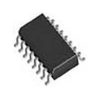
LTC1235CS Linear Technology, LTC1235CS Datasheet - Page 8

LTC1235CS
Manufacturer Part Number
LTC1235CS
Description
Manufacturer
Linear Technology
Datasheet
1.LTC1235CS.pdf
(16 pages)
Specifications of LTC1235CS
Number Of Elements
1
Monitored Voltage 1 (typ)
4.65V
Battery Backup Switching
Yes
Watchdog Timer
Yes
Chip Enable Signals
Yes
Reset Active Time
280ms
Manual Reset
Yes
Package Type
SOL
Operating Supply Voltage (min)
4.75V
Operating Supply Voltage (max)
5.5V
Reset Threshold Voltage (max)
4.75V
Reset Threshold Voltage (min)
4.5V
Power Dissipation
500mW
Operating Temp Range
0C to 70C
Operating Temperature Classification
Commercial
Power Fail Detection
Yes
Mounting
Surface Mount
Pin Count
16
Supply Current
1.5mA
Lead Free Status / Rohs Status
Not Compliant
Available stocks
Company
Part Number
Manufacturer
Quantity
Price
Part Number:
LTC1235CS
Manufacturer:
LINEAR/凌特
Quantity:
20 000
Part Number:
LTC1235CS#TRPBF
Manufacturer:
LTNEAR
Quantity:
20 000
Part Number:
LTC1235CSW
Manufacturer:
LINEAR/凌特
Quantity:
20 000
Part Number:
LTC1235CSW#PBF
Manufacturer:
LINEAR/凌特
Quantity:
20 000
Part Number:
LTC1235CSW#TR
Manufacturer:
LT/凌特
Quantity:
20 000
LTC1235
APPLICATIONS INFORMATION
Power Monitoring
The LTC1235 uses a bandgap voltage reference and a
precision voltage comparator C1 to monitor the 5V supply
input on V
the reset voltage threshold, the reset outputs are forced
to active states. The reset voltage threshold accounts for
a 5% variation on V
when V
the reset signals are held active states for a minimum
of 140ms after the reset voltage threshold is reached to
allow the power supply and microprocessor to stabilize.
On power-down, the RESET signal remains active low
even with V
the microprocessor in stable shutdown condition. Figure
1 shows the timing diagram of the RESET signal.
The precision voltage comparator, C1, typically has 40mV
of hysteresis which ensures that glitches at V
activate the reset outputs. Response time is typically 10μs.
8
CC
falls below 4.75V (4.65V typical). On power-up,
CC
CC
(see Block Diagram). When V
as low as 1V. This capability helps hold
LOW LINE
RESET
CC
V
CC
, so the reset outputs become active
V
PB RST
RESET
RESET
CC
= 5V
V2
t1
CC
CC
LOGIC LOW
falls below
Figure 1. Reset Active Time
pin do not
Figure 2. Push-Button Reset
t1
t1 = PUSH-BUTTON RESET LOW TIME
t2 = RESET ACTIVE TIME
V1
V2
To help prevent mistriggering due to transient loads, V
pin should be bypassed with a 0.1μF capacitor with the
leads trimmed as short as possible.
LOW LINE is the output of the precision voltage compara-
tor C1. When V
LOW LINE goes low. LOW LINE returns high as soon as
V
Push-Button Reset
The LTC1235 provides an logic input pin for direct con-
nection to a push-button. The push-button reset input,
PB RST, requires an active low signal. Internally, this input
signal is debounced and timed for a minimum of 40ms.
When this condition is satisfi ed, the reset pulse generator
forces the reset outputs to active states. The reset signals
will remain in active states for a minimum of 140ms from
the moment the push-button reset input is released from
logic low level (Figure 2).
CC
LOGIC
HIGH
rises above the reset voltage threshold.
t1 = RESET ACTIVE TIME
V1 = RESET VOLTAGE THRESHOLD
V2 = RESET VOLTAGE THRESHOLD +
RESET THRESHOLD HYSTERESIS
t1
LOGIC HIGH
LOGIC LOW
t2
CC
falls below the reset voltage threshold,
1235 F02
V1
1235 F01
1235fa
CC


