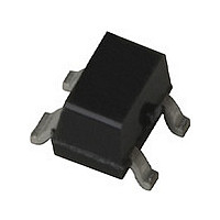
MSA-2643-BLK Avago Technologies US Inc., MSA-2643-BLK Datasheet - Page 13

MSA-2643-BLK
Manufacturer Part Number
MSA-2643-BLK
Description
Manufacturer
Avago Technologies US Inc.
Datasheet
1.MSA-2643-BLK.pdf
(15 pages)
Specifications of MSA-2643-BLK
Manufacturer's Type
MMIC Amplifier
Number Of Channels
1
Supply Current
70mA
Frequency (max)
6GHz
Operating Supply Voltage (min)
3V
Operating Supply Voltage (typ)
3.4V
Operating Supply Voltage (max)
3.8V
Package Type
SOT-343
Mounting
Surface Mount
Pin Count
3 +Tab
Noise Figure (typ)
3.6@2000MHzdB
Lead Free Status / Rohs Status
Not Compliant
13
Values for most of the parameters
in the table of Electrical Specifica-
tions that are described by typical
data are the mathematical mean
(µ), of the normal distribution tak-
en from the characterization data.
For parameters where measure-
ments or mathematical averaging
may not be practical, such as S-pa-
rameters or Noise Parameters and
the performance curves, the data
represents a nominal part taken
from the center of the character-
ization distribution. Typical values
are intended to be used as a basis
for electrical design.
To assist designers in optimizing
not only the immediate ampli-
fier circuit using the MSA-2643,
but to also evaluate and optimize
trade-offs that affect a complete
wireless system, the standard
deviation (σ) is provided for many
of the Electrical Specifications
parameters (at 25°C) in addition
to the mean. The standard devia-
tion is a measure of the variability
about the mean. It will be recalled
that a normal distribution is com-
pletely described by the mean and
standard deviation.
Standard statistics tables or calcu-
lations provide the probability of
a parameter falling between any
two values, usually symmetrically
located about the mean. Refer-
ring to Figure 10 for example, the
probability of a parameter being
between ±1σ is 68.3%; between
±2σ is 95.4%; and between ±3σ is
99.7%.
Figure 10. Normal Distribution.
-3σ
-2σ
-1σ
Parameter Value
68%
95%
99%
(µ), typ
Mean
+1σ +2σ +3σ
Phase Reference Planes
The positions of the reference
planes used to specify S-pa-
rameters for the MSA-2643 are
shown in Figure 11. As seen in the
illustration, the reference planes
are located at the point where the
package leads contact the test
circuit for the RF input and RF
output/bias. As noted under the
s-parameter table in section one of
the data sheet the MSA-2643 was
tested in a fixture that includes
plated through holes through a
0.025" thickness printed circuit
board. Due to the complexity of
de-embedding these grounds, the
S-parameters include the effects
of the test fixture grounds. There-
fore, when simulating the perfor-
mance of the MSA-2643 the added
ground path inductance should be
taken into account. For example
if you were designing an amplifier
on 0.031" thickness printed circuit
board material, only the differ-
ence in the printed circuit board
thickness needs to be included in
the simulation, i.e. 0.031" – 0.025"
=0.006".
Figure 11. Phase Reference Planes.
Test Fixture
Reference
Vias
Plane
Input
TEST FIXTURE
Output
Reference
Plane
Test Fixture
Vias
References
Performance data for MSA series
of amplifiers are found in the
CD ROM Catalog or http://www.
Avagotech.com/view/rf
Application Notes
AN-S001: Basic MODAMP MMIC
Circuit Techniques
AN-S002: MODAMP MMIC
Nomenclature
AN-S003: Biasing MODAMP MMICs
AN-S011: Using Silicon MMIC Gain
Blocks as Transimpedance Amplifiers
AN-S012: MagIC Low Noise Amplifiers


