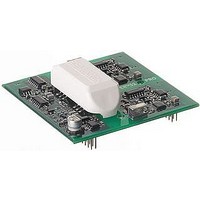
SKYPER 32 PRO SEMIKRON, SKYPER 32 PRO Datasheet - Page 9

SKYPER 32 PRO
Manufacturer Part Number
SKYPER 32 PRO
Description
16M0274
Manufacturer
SEMIKRON
Datasheet
1.SKYPER_32_PRO.pdf
(18 pages)
Specifications of SKYPER 32 PRO
Device Type
IGBT
Module Configuration
Half Bridge
Peak Output Current
15A
Input Delay
1.2µs
Output Delay
1.2µs
Supply Voltage Range
14.4V To 15.6V
No. Of Pins
20
Rohs Compliant
Yes
Under Voltage Reset (UVR)
The Under Voltage Reset circuit configures the driver core to hold in a reset state during power on and power off. UVR can
be thought of as a supplement function to the build in power-on-reset by the user. While in reset, the driver is held in its initial
condition until PRIM_nPWRFAIL_IN is forced into HIGH state. Once the system reset sequence completes, the driver core
is ready to operate.
Under Voltage Protection (UVP) primary
The internally detected supply voltage of the driver has an under voltage protection. The table below gives an overview of
the trip level.
If the internally detected supply voltage of the driver falls below this level, the IGBTs will be switched off (IGBT driving
signals set to LOW). The input side switching signals of the driver will be ignored. The error memory will be set, and the
output PRIM_HOLD_OUT changes to the HIGH state.
Under Voltage Protection secondary
This function monitors the rectified voltage on the secondary side. If the voltage drops, the IGBTs will be switched off (IGBT
driving signal set to LOW). The input side switching signals of the driver will be ignored. No failure message will be
generated.
Input Signals
The signal transfer to each IGBT is made with pulse transformers, used for switching on and switching off of the IGBT. The
inputs have a Schmitt Trigger characteristic and a positive / active high logic (input HIGH = IGBT on; input LOW = IGBT off).
It is mandatory to use circuits which switch active to +15V and 0V. Pull up and open collector output stages must not be
used for TOP / BOT control signals. It is recommended choosing the line drivers according to the demanded length of the
signal wires.
SKYPER™ 32PRO R
UVR input
Supply voltage
Regulated +15V ±4%
Output voltage
Regulated +15V
9
Please note:
Do not use PRIM_nPWRFAIL_IN to place the driver core into halt mode during operation.
Please note:
It is not permitted to apply switching pulses shorter than 1µs.
UVP level
UVP level
13,5V
12V
2007-01-19 – Rev03
Application Hints
A capacitor is connected to the input to obtain high noise
immunity.
Disabling
(PRIM_nPWRFAIL_IN) can be achieved by no connection or
connection to +15V.
of
the
Under
Voltage
© by SEMIKRON
Reset
function


