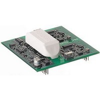
SKYPER 32 PRO SEMIKRON, SKYPER 32 PRO Datasheet - Page 7

SKYPER 32 PRO
Manufacturer Part Number
SKYPER 32 PRO
Description
16M0274
Manufacturer
SEMIKRON
Datasheet
1.SKYPER_32_PRO.pdf
(18 pages)
Specifications of SKYPER 32 PRO
Device Type
IGBT
Module Configuration
Half Bridge
Peak Output Current
15A
Input Delay
1.2µs
Output Delay
1.2µs
Supply Voltage Range
14.4V To 15.6V
No. Of Pins
20
Rohs Compliant
Yes
Driver Performance
The driver is designed for application with half bridges or single modules and a maximum gate charge per pulse
< 6,3µC. The charge necessary to switch the IGBT is mainly depending on the IGBT’s chip size, the DC-link voltage and the
gate voltage. This correlation is shown in module datasheets. It should, however, be considered that the driver is turned on
at +15V and turned off at -7V. Therefore, the gate voltage will change by 22V during each switching procedure.
Unfortunately, many datasheets do not show negative gate voltages. In order to determine the required charge, the upper
leg of the charge curve may be prolonged to +22V for determination of approximate charge per switch.
The medium output current of the driver is determined by the switching frequency and the gate charge. The maximum
switching frequency may be calculated with the shown equations and is limited by the average current of the driver power
supply and the power dissipation of driver components.
Insulation
Magnetic transformers are used for insulation between gate driver primary and secondary side. The transformer set consists
of pulse transformers which are used bidirectional for turn-on and turn-off signals of the IGBT and the error feedback
between secondary and primary side, and a DC/DC converter. This converter provides a potential separation (galvanic
separation) and power supply for the two secondary (TOP and BOT) sides of the driver. Thus, external transformers for
power supply are not required.
f
Iout
Q
*@ T
Calculation Average Output Current
Iout
f
Q
SKYPER™ 32PRO R
Calculation Switching Frequency
Creepage and Clearance Distance in mm
Primary to secondary
7
max
sw
Please note:
The maximum value of the switching frequency is limited to 50kHz due to switching reasons.
GE
GE
:
:
AVmax
:
AV
:
amb
:
=25°C
: Maximum output average current
Gate charge of the driven IGBT
Switching frequency
Average output current
Gate charge of the driven IGBT
Maximum switching frequency *
f
Iout
max
=
AV
Iout
=
Q
f
AV
GE
sw
max
×
Q
GE
Average Output Current as a Function of the Ambient Temperature
Maximum Switching Frequency @ different Gate Charges @ T
2007-01-19 – Rev03
60 mA
50 mA
40 mA
30 mA
20 mA
10 mA
60 kHz
50 kHz
40 kHz
30 kHz
20 kHz
10 kHz
0 mA
0 kHz
0 °C
0 µC
Min. 12,2
10 °C
1 µC
20 °C
2 µC
30 °C
ambient temperature
3 µC
40 °C
gate charge
50 °C
4 µC
60 °C
5 µC
70 °C
amb
© by SEMIKRON
6 µC
=25°C
80 °C
90 °C
7 µC


