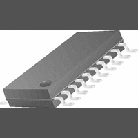
LMX2352TM National Semiconductor, LMX2352TM Datasheet - Page 12

LMX2352TM
Manufacturer Part Number
LMX2352TM
Description
07B5847
Manufacturer
National Semiconductor
Datasheet
1.LMX2352TMNOPB.pdf
(21 pages)
Specifications of LMX2352TM
Pll Type
Frequency Synthesis
Frequency
1.2GHz
Supply Current
4.75mA
Supply Voltage Range
2.7V To 5.5V
Digital Ic Case Style
TSSOP
No. Of Pins
24
Rohs Compliant
No
Available stocks
Company
Part Number
Manufacturer
Quantity
Price
Company:
Part Number:
LMX2352TM/NOPB
Manufacturer:
TI/NSC
Quantity:
1 000
Part Number:
LMX2352TMB
Manufacturer:
NS/国半
Quantity:
20 000
Company:
Part Number:
LMX2352TMX
Manufacturer:
NS/TI
Quantity:
3
Part Number:
LMX2352TMX
Manufacturer:
NS/国半
Quantity:
20 000
Company:
Part Number:
LMX2352TMX/NOPB
Manufacturer:
ST
Quantity:
7 600
www.national.com
Programming Description
2.0 INPUT DATA REGISTER
The descriptions below describe the 24-bit data register loaded through the MICROWIRE Interface. The data register is used to
program the 15-bit IF_R counter register, and the 15-bit RF_R counter register, the 15-bit IF_N counter register, and the 19-bit
RF_N counter register. The data format of the 24-bit data register is shown below. The control bits CTL [1:0] decode the internal
register address. On the rising edge of LE, data stored in the shift register is loaded into one of the 4 appropriate latches (selected
by address bits). Data is shifted in MSB first
2.1 Register Location Truth Table
2.2 Register Content Truth Table
3.0 PROGRAMMABLE REFERENCE DIVIDERS
3.1 IF_R Register
If the Control Bits (CTL [1:0]) are 0 0, when LE is transitioned high data is transferred from the 24-bit shift register into a latch
which sets the IF PLL 15-bit R counter divide ratio. The divide ratio is programmed using the bits IF_R_CNTR as shown in table
3.1.3. The ratio must be
OSC bit is used to enable the crystal oscillator mode. FoLD [2:0] is used to set the function of the Lock Detect output (pin 11),
according to table 3.1.3.
3.1.1 OSC
The OSC bit, IF_R [23], selects whether the oscillator input pins OSCin and OSCx drive the IF and RF R counters separately or
by a common input signal path. When the OSC bit = 1, a crystal resonator can be connected between OSCin and OSCx together
with 2 capacitors to form a crystal oscillator. When OSC = 0 , the OSCin pin drives the IF R counter while the OSCx drives the
RF R counter.
3.1.2 FRAC_16
The FRAC_16 bit, IF_R [22], is used to set the fractional compensation at either 1/16 and 1/15 resolution. When FRAC-16 is set
to one, the fractional modulus is set to 1/16 resolution, and FRAC_16 = 0 corresponds to 1/15 (See section 4.2.4).
RF_R DLL_MODE
RF_N
IF_R
IF_N
MSB
23
MSB
OSC
23
OSC
23
RF_CTL_WORD
IF_CTL_WORD
FRAC_16
22
First Bit
1
0
0
1
1
(IF_R[23])
FRAC_16
V2_EN
22
3. The IF_CP_WORD [1:0], programs the IF charge pump magnitude and polarity shown in 3.1.4. The
(IF_R[22])
FoLD [2:0]
21
DATA [21:0]
21 20 19
CTL [1:0]
FoLD
RF_CP_WORD
19
IF_CP_WORD
CMOS
18
IF_CP_WORD [1:0]
18
RF_NB_CNTR
17
0
0
1
0
1
16 15 14 13 12 11 10 9 8 7 6 5
REGISTER BIT LOCATION
12
17
2
IF_NB_CNTR
1
CTL [1:0]
IF_R_CNTR [14:0]
16
RF_R_CNTR
IF_R_CNTR
RF_NA_CNTR
LSB
0
DATA Location
IF_R register
IF_N register
RF_R register
RF_N register
2
FRAC_CNTR
IF_NA_CNTR 0 1
4
3
0
1
Last Bit
2
LSB
0
0
1 0
0 0
1 0
1 1


