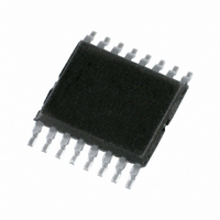
74HC4852PW,118 NXP Semiconductors, 74HC4852PW,118 Datasheet - Page 11

74HC4852PW,118
Manufacturer Part Number
74HC4852PW,118
Description
IC MUX/DEMUX DUAL 4X1 16TSSOP
Manufacturer
NXP Semiconductors
Series
74HCr
Type
Analog Multiplexerr
Specifications of 74HC4852PW,118
Package / Case
16-TSSOP (0.173", 4.40mm Width)
Function
Multiplexer/Demultiplexer
Circuit
2 x 4:1
On-state Resistance
59 Ohm
Voltage Supply Source
Single Supply
Voltage - Supply, Single/dual (±)
2 V ~ 6 V
Current - Supply
2µA
Operating Temperature
-40°C ~ 125°C
Mounting Type
Surface Mount
Number Of Channels
2 Channel
On Resistance (max)
650 Ohm @ 2 V
On Time (max)
47.5 ns @ 2 V
Off Time (max)
100 ns @ 2 V
Supply Voltage (max)
6 V
Supply Voltage (min)
2 V
Maximum Power Dissipation
500 mW
Maximum Operating Temperature
+ 125 C
Minimum Operating Temperature
- 40 C
Mounting Style
SMD/SMT
Number Of Switches
Dual
Package
16TSSOP
Maximum On Resistance
650@2V Ohm
Maximum Propagation Delay Bus To Bus
38@2V|20@3V|17.5@3.3V|14@4.5V|12.6@6V ns
Maximum Low Level Output Current
25 mA
Multiplexer Architecture
4:1
Maximum Turn-off Time
100@2V ns
Maximum Turn-on Time
47.5@2V ns
Power Supply Type
Single
Lead Free Status / RoHS Status
Lead free / RoHS Compliant
Lead Free Status / RoHS Status
Lead free / RoHS Compliant, Lead free / RoHS Compliant
Other names
74HC4852PW-T
74HC4852PW-T
935282089118
74HC4852PW-T
935282089118
Available stocks
Company
Part Number
Manufacturer
Quantity
Price
Company:
Part Number:
74HC4852PW,118
Manufacturer:
TexasInstruments
Quantity:
285
NXP Semiconductors
11. Dynamic characteristics
Table 9.
GND = 0 V; C
74HC4852_2
Product data sheet
Symbol Parameter
V
t
t
t
V
t
t
t
V
t
t
t
V
t
t
t
pd
en
dis
pd
en
dis
pd
en
dis
pd
en
dis
CC
CC
CC
CC
= 2.0 V
= 3.0 V
= 3.3 V
= 4.5 V
propagation delay see
enable time
disable time
propagation delay see
enable time
disable time
propagation delay see
enable time
disable time
propagation delay see
enable time
disable time
Dynamic characteristics
L
= 50 pF; R
L
= 10 k unless specified otherwise; for test circuit see
Conditions
nZ, nYn to nYn, nZ
Sn to nZ, nYn
see
E to nZ, nYn
see
E to nZ, nYn
nZ, nYn to nYn, nZ
Sn to nZ, nYn
see
E to nZ, nYn
see
E to nZ, nYn
nZ, nYn to nYn, nZ
Sn to nZ, nYn
see
E to nZ, nYn
see
E to nZ, nYn
nZ, nYn to nYn, nZ
Sn to nZ, nYn
see
E to nZ, nYn
see
E to nZ, nYn
Figure 10
Figure 11
Figure 11
Figure 10
Figure 11
Figure 11
Figure 10
Figure 11
Figure 11
Figure 10
Figure 11
Figure 11
4-channel analog MUX/DEMUX with injection-current effect control
Rev. 02 — 30 May 2007
[1]
[2]
[3]
[1]
[2]
[3]
[1]
[2]
[3]
[1]
[2]
[3]
10.5
39.5
35.2
34.6
28.5
Min
2.2
7.7
2.2
4.9
6.2
2.0
4.4
5.6
1.6
3.2
4.2
25 C
16.8
20.5
75.4
10.6
69.5
68.1
Typ
9.3
4.9
8.8
4.4
7.9
9.4
3.2
5.8
6.9
63
Max
47.5
16.5
15.0
17.5
42.5
11.6
100
33
38
20
45
90
85
14
40
80
39.3
35.5
34.6
28.2
40 C to +85 C
Min
2.2
6.3
8.5
1.9
3.9
5.2
1.6
3.4
4.6
1.1
2.3
3
Figure
12.
Max
52.5
21.5
16.5
47.5
12.5
105
100
34
40
18
50
19
95
15
45
90
40 C to +125 C Unit
34.5
Min
74HC4852
2.2
6.3
8.5
1.9
3.9
5.2
1.6
3.4
4.6
1.1
2.3
35
28
39
3
© NXP B.V. 2007. All rights reserved.
Max
57.5
19.5
18.5
52.5
13.5
115
110
105
100
35
42
23
55
22
17
50
11 of 20
ns
ns
ns
ns
ns
ns
ns
ns
ns
ns
ns
ns
ns
ns
ns
ns


