EA-XPR-006 Embedded Artists, EA-XPR-006 Datasheet - Page 21
EA-XPR-006
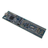
Manufacturer Part Number
EA-XPR-006
Description
BOARD LPCXPRESSO LPC11C24
Manufacturer
Embedded Artists
Specifications of EA-XPR-006
Lead Free Status / Rohs Status
Lead free / RoHS Compliant


NXP Semiconductors
LPC11CX2_CX4
Product data sheet
7.11.2.6 Time-out function
7.12.1 Features
7.13.1 Features
7.12 10-bit ADC
7.13 General purpose external event counter/timers
A ‘TXD dominant time-out’ timer is started when the CAN_TXD signal of the C_CAN
controller is set LOW. If the LOW state on the CAN_TXD signal persists for longer than
t
function prevents a hardware and/or software application failure from driving the bus lines
to a permanent dominant state (blocking all network communications). The TXD dominant
time-out timer is reset when the CAN_TXD signal is set HIGH. The TXD dominant
time-out time also defines the minimum possible bit rate of 40 kbit/s.
The LPC11Cx2/Cx4 contains one ADC. The ADC is a single 10-bit successive
approximation ADC with eight channels.
The LPC11Cx2/Cx4 includes two 32-bit counter/timers and two 16-bit counter/timers. The
counter/timer is designed to count cycles of the system derived clock. It can optionally
generate interrupts or perform other actions at specified timer values, based on four
match registers. Each counter/timer also includes one capture input to trap the timer value
when an input signal transitions, optionally generating an interrupt.
to(dom)TXD
•
•
•
•
•
•
•
•
•
•
•
•
•
10-bit successive approximation ADC.
Input multiplexing among 8 pins.
Power-down mode.
Measurement range 0 V to V
10-bit conversion time 2.44 s (up to 400 kSamples/s).
Burst conversion mode for single or multiple inputs.
Optional conversion on transition of input pin or timer match signal.
Individual result registers for each ADC channel to reduce interrupt overhead.
A 32-bit/16-bit timer/counter with a programmable 32-bit/16-bit prescaler.
Counter or timer operation.
One capture channel per timer, that can take a snapshot of the timer value when an
input signal transitions. A capture event may also generate an interrupt.
Four match registers per timer that allow:
– Continuous operation with optional interrupt generation on match.
– Stop timer on match with optional interrupt generation.
– Reset timer on match with optional interrupt generation.
Up to four external outputs corresponding to match registers, with the following
capabilities:
– Set LOW on match.
– Set HIGH on match.
, the transmitter is disabled, releasing the bus lines to recessive state. This
All information provided in this document is subject to legal disclaimers.
Rev. 3 — 27 June 2011
DD
.
32-bit ARM Cortex-M0 microcontroller
LPC11Cx2/Cx4
© NXP B.V. 2011. All rights reserved.
21 of 62
Related parts for EA-XPR-006
Image
Part Number
Description
Manufacturer
Datasheet
Request
R

Part Number:
Description:
BOARD LPCXPRESSO LPC1343
Manufacturer:
Embedded Artists
Datasheet:
Part Number:
Description:
BOARD LPCXPRESSO LPC1114
Manufacturer:
Embedded Artists
Datasheet:
Part Number:
Description:
BOARD LPCXPRESSO LPC1768
Manufacturer:
Embedded Artists
Datasheet:
Part Number:
Description:
KIT LPCXPRESSO MOTOR CONTROL
Manufacturer:
Embedded Artists
Datasheet:
Part Number:
Description:
BOARD LPCXPRESSO LPC11U14
Manufacturer:
Embedded Artists
Datasheet:

Part Number:
Description:
BOARD LPCXPRESSO LPC1227
Manufacturer:
Embedded Artists
Datasheet:
Part Number:
Description:
Development Boards & Kits - ARM LPCXpresso Experiment Kit
Manufacturer:
Embedded Artists
Part Number:
Description:
Development Boards & Kits - ARM LPC1115 LPCXPRESSO Board
Manufacturer:
Embedded Artists
Part Number:
Description:
Development Boards & Kits - ARM LPC1347 LPCXPRESSO BOARD
Manufacturer:
Embedded Artists
Part Number:
Description:
Development Boards & Kits - ARM LPC1227 LPCXPRESSO LPC-LINK
Manufacturer:
Embedded Artists

Part Number:
Description:
MIC ELECTRET PORT ON SIDE DAMPED
Manufacturer:
Knowles Acoustics
Datasheet:
Part Number:
Description:
Microphones 5.56 X 3.98 X 2.21MM -61 SENS, 12S PORT
Manufacturer:
Knowles Acoustics
Datasheet: