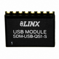
SDM-USB-QS-S_ Linx Technologies Inc, SDM-USB-QS-S_ Datasheet - Page 6

SDM-USB-QS-S_
Manufacturer Part Number
SDM-USB-QS-S_
Description
MODULE USB LOW SPEED
Manufacturer
Linx Technologies Inc
Series
QSr
Datasheet
1.SDM-USB-QS-S_.pdf
(7 pages)
Specifications of SDM-USB-QS-S_
Applications
USB, Peripherals
Interface
Parallel/Serial
Voltage - Supply
4.35 V ~ 5.25 V
Package / Case
16-SMD Module
Mounting Type
Surface Mount
Lead Free Status / RoHS Status
Lead free / RoHS Compliant
Other names
SDM-USB-QS-S
SDM-USB-QS-S
SDM-USB-QS1-S
SDM-USB-QS-S
SDM-USB-QS1-S
TYPICAL APPLICATIONS (CONT.)
Figure 11: Interface With A Microprocessor
SOFTWARE CONSIDERATIONS
Page 10
Figure 11 below shows the QS module connected to a microprocessor. This is
the design used in the QS Master Development Kit and the documentation for
the kit describes the connections and software.
The PC needs a set of drivers that tell it how to communicate with the QS
module. The CDM drivers for the QS Series module actually install two different
drivers at the same time. The first driver makes the QS appear as an extra COM
port on the host PC. This allows the application to use standard writes and reads
to a serial port, and the drivers will redirect data to the USB device.
The second driver supports a series of functions that allow more direct control of
the QS module. These functions are described in Application Note AN-00200:
SDM-USB-QS-S Programmer's Guide, where examples are given in both Visual
Basic and C. The Programmer's Guide can be downloaded from the Application
Notes
www.linxtechnologies.com. Sample software is available on the Software page
in the Support section.
In addition to the Programmer's Guide, the QS Master Development System
(MDEV-USB-QS) includes example software and sample system source code.
This source code provides the driver function declarations, examples of how to
use the functions in a program, and other code that may be of use.
USB Type B
Connector
page
DAT+
DAT -
GND
VCC
5V
4
3
2
1
in
220
220
the
1
2
3
4
5
6
7
8
220
220
220
USBDP
USBDM
GND
VCC
SUSP_IND
RX_IND
TX_IND
485_TX
Support
SDM-USB-QS-S
1
2
3
4
5
6
7
8
9
RA2/AN2
RA3/AN3
RA4/AN4
MCLR/VPP
GND
RB0/INT
RB1
RB2/RX
RB3
DATA_OUT
DATA_IN
PIC16F88
DCD
DSR
RTS
CTS
DTR
section
RI
16
15
14
13
12
11
10
9
RA1/AN1
RB5/TX
VCC
RA7
RA6
RB7
RB6
RB4
220
220
VCC
of
18
17
16
15
14
13
12
11
10
VCC
the
10K
VCC
Linx
SW-PB
200K
website
at
SERIAL NUMBER CONSIDERATIONS
HELPFUL APPLICATION NOTES FROM LINX
The VID and PID are used by Windows to determine what devices are attached
to the bus and which drivers to load in order to communicate with each device.
A unique serial number is used to distinguish between different devices of the
same type so that the operating system can be sure that it is communicating with
the correct one. Windows will view every different combination of VID, PID, and
serial number as a new device and will start the “Found New Hardware” wizard
for each one. This is an issue in a mass production environment, so the QS
modules are shipped with the “Enable Serial Number” option disabled in the
EEPROM. This prevents the serial number from being used during
ennumeration.
With the serial number disabled, Windows will track each device by connection
and assign a USB port to a particular device. If the device is moved to another
port, it will need to be reinstalled. The problem that arises is that the device will
be installed on the same PC multiple times, once for each USB port into which it
has been plugged.
It is recommended to set the “Enable Serial Number” option and to use a unique
serial number as a part of the final testing procedure of your product. The QS
EEPROM Programmer can be downloaded from the Linx website and the
EEPROM programming functions can be found in Application Note AN-00200.
These can be used as a part of an automated test program at the end of the
production line to program custom descriptors and a unique serial number into
the product.
Avoid using the same serial number for multiple devices, as it can cause a
conflict in the operating system. Windows XP has a particular problem with this
and may crash if it sees two of the same type of device with the same serial
number on the same bus.
It is not the intention of this manual to address in depth many of the issues that
should be considered to ensure that the modules function correctly and deliver
the maximum possible performance. As you proceed with your design, you may
wish to obtain the following application notes. They are available on line at
www.linxtechnologies.com or by contacting the Linx literature department.
AN-00200
AN-00201
NOTE
SDM-USB-QS-S Programmer’s Guide
Installing the SDM-USB-QS-S Drivers
APPLICATION NOTE TITLE
Page 11


