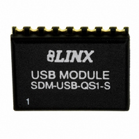
SDM-USB-QS-S_ Linx Technologies Inc, SDM-USB-QS-S_ Datasheet - Page 4

SDM-USB-QS-S_
Manufacturer Part Number
SDM-USB-QS-S_
Description
MODULE USB LOW SPEED
Manufacturer
Linx Technologies Inc
Series
QSr
Datasheet
1.SDM-USB-QS-S_.pdf
(7 pages)
Specifications of SDM-USB-QS-S_
Applications
USB, Peripherals
Interface
Parallel/Serial
Voltage - Supply
4.35 V ~ 5.25 V
Package / Case
16-SMD Module
Mounting Type
Surface Mount
Lead Free Status / RoHS Status
Lead free / RoHS Compliant
Other names
SDM-USB-QS-S
SDM-USB-QS-S
SDM-USB-QS1-S
SDM-USB-QS-S
SDM-USB-QS1-S
MODULE DESCRIPTION
INSTALLING THE DRIVERS
Figure 6: Windows XP Driver Error Window
Page 6
The Linx SDM-USB-QS-S module will convert USB signals from a host, such as
a PC or hub, into TTL logic level signals. This enables the module to be
connected directly to microcontrollers (or Linx RF modules for wireless
applications) or to RS-232 or RS-485 level converters for communication with
legacy devices. The module handles all of the complicated enumeration and bus
communication processes, freeing the designer to focus on handling the data. All
necessary firmware is included in the module and the device descriptors can
easily be changed to customize the device.
The host application software can access the USB device by simple, custom
functions or by standard Windows Win32 API calls. In addition, Virtual COM Port
drivers are available that make the USB module appear to the PC as an
additional COM port, without the need for additional system resources, such as
an IRQ or address. This allows the designer to program the application software
to use standard serial or parallel ports and then simply select the port that
represents the USB module. The drivers will automatically direct the data to the
USB bus and the device.
The drivers for the USB module are included with the module’s
development system or may be downloaded from the Linx website at
www.linxtechnologies.com. These drivers should be downloaded onto the hard
drive of a PC or onto a disk. When the module is attached to the PC for the first
time, Windows will automatically detect the device and search for the best driver.
Windows will prompt for the location of the drivers, so browse to the folder or the
disk, click Next, and Windows will do the rest. Windows XP may return an error
window as shown in the figure below.
This window is simply a warning that the driver has not gone through Microsoft’s
certification process and could potentially pose a problem for the system. The
drivers provided for the QS module have been independently tested and should
not pose any problems unless modified by the user. Click the Continue Anyway
button to finish the installation process.
THEORY OF OPERATION
Figure 7: SDM-USB-QS-S Block Diagram
USBDM
USBDP
Figure 7 below shows a block diagram of the QS module.
The USB transceiver block provides the physical interface for the USB signalling.
The USB DPLL locks onto the NRZ data and provides separate recovered clock
and data signals to the Serial Interface Engine (SIE).
The SIE performs the parallel-to-serial and serial-to-parallel conversion, bit-
stuffing / un-stuffing, and CRC calculations on the USB data.
The USB Protocol Engine manages the data from the USB control endpoint, the
USB protocol requests from the USB host controller, and the commands for
controlling the functional parameters of the UART.
Data from the USB data out endpoint is stored in the TX buffer and removed from
the buffer to the UART transmit register under control of the UART FIFO
controller.
Data from the UART receive register is stored in the RX buffer prior to being
removed by the SIE on a USB request for data from the device data in endpoint.
The UART FIFO controller handles the transfer of data between the RX and TX
buffers and the UART transmit and receive registers.
The UART performs asynchronous 7 / 8 bit parallel-to-serial and serial-to-parallel
conversion of the data on the RS-232 interface. Control signals supported by the
UART include RTS, CTS, DSR , DTR, DCD, and RI. The UART provides a
transmitter-enable control signal (485_TX) to assist with interfacing to RS-485
transceivers. The UART supports RTS / CTS, DSR / DTR and X-On / X-Off
handshaking options. Handshaking, where required, is handled in hardware to
ensure fast response times. The UART also supports the RS-232 BREAK setting
and detection conditions.
GND
VCC
Transceiver
USB DPLL
Clock
USB
Serial Interface
Engine (SIE)
SUSP_IND
USB Protocol
TX Buffer
128 Bytes
RX Buffer
384 Bytes
Engine
UART FIFO
Controller
UART
DATA_OUT
DATA_IN
RTS
CTS
DTR
DSR
DCD
RI
485_TX
TX_IND
RX_IND
Page 7


