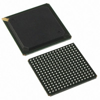
PI7C9X20508GPBNDE Pericom Semiconductor, PI7C9X20508GPBNDE Datasheet - Page 54

PI7C9X20508GPBNDE
Manufacturer Part Number
PI7C9X20508GPBNDE
Description
IC PCIE PACKET SWITCH 256BGA
Manufacturer
Pericom Semiconductor
Series
GreenPacket™r
Specifications of PI7C9X20508GPBNDE
Applications
Data Transport
Interface
Advanced Configuration Power Interface (ACPI)
Package / Case
256-PBGA
Mounting Type
Surface Mount
Lead Free Status / RoHS Status
Lead free / RoHS Compliant
Voltage - Supply
-
Available stocks
Company
Part Number
Manufacturer
Quantity
Price
Company:
Part Number:
PI7C9X20508GPBNDE
Manufacturer:
Pericom
Quantity:
200
7.2.68
June 2009 – Revision 1.5
Pericom Semiconductor
LINK CAPABILITIES REGISTER – OFFSET ECh
BIT
17
18
19
20
21
31:22
BIT
3:0
11:10
14:12
17:15
19:18
9:4
FUNCTION
Non-Fatal Error
Detected
Fatal Error Detected
Unsupported Request
Detected
AUX Power
Detected
Transactions Pending
Reserved
FUNCTION
Maximum Link
Speed
Maximum Link
Width
Active State Power
Management
(ASPM) Support
L0s Exit Latency
L1 Exit
Latency
Reserved
RW1C
RW1C
RW1C
TYPE
TYPE
RO
RO
RO
RO
RO
RO
RO
RO
RO
Page 54 of 81
DESCRIPTION
Asserted when non-fatal error is detected. Errors are logged in this register
regardless of whether error reporting is enabled or not in the Device Control
register.
Reset to 0b.
Asserted when fatal error is detected. Errors are logged in this register
regardless of whether error reporting is enabled or not in the Device Control
register.
Reset to 0b.
Asserted when unsupported request is detected. Errors are logged in this
register regardless of whether error reporting is enabled or not in the Device
Control register.
Reset to 0b.
Asserted when the AUX power is detected by the switch
Reset to 1b.
Each port of switch does not issue Non-posted Requests on its own behalf, so
this bit is hardwired to 0b.
Reset to 0b.
Reset to 0.
DESCRIPTION
Read as 0001b to indicate the maximum speed of the Express link is 2.5 Gb/s.
Indicates the maximum width of the given PCIe Link. The width of each port
is determined by strapped pin or EEPROM pre-loaded value.
Reset to 000100b (x4) for Port 0.
Reset to 000001b (x1) for Port 1.
Reset to 000001b (x1) for Port 2.
Reset to 000001b (x1) for Port 3.
Reset to 000001b (x1) for Port 4.
Indicates the level of ASPM supported on the given PCIe Link. Each port of
switch supports L0s and L1 entry. The default value may be changed by
SMBus or auto-loading from EEPROM.
Reset to 01b.
Indicates the L0s exit latency for the given PCIe Link.
The length of time this port requires to complete transition from L0s to L0 is
in the range of 256ns to less than 512ns. The default value may be changed
by SMBus or auto-loading from EEPROM.
Reset to 011b.
Indicates the L1 exit latency for the given PCIe Link.
The length of time this port requires to complete transition from L1 to L0 is in
the range of 16us to less than 32us. The default value may be changed by
SMBus or auto-loading from EEPROM.
Reset to 000b.
Reset to 00b.
5Port-8Lane PCI Express Switch
GreenPacket
PI7C9X20508GP
Datasheet
TM
Family


