PX1011BI-EL1/G,551 NXP Semiconductors, PX1011BI-EL1/G,551 Datasheet - Page 21
PX1011BI-EL1/G,551
Manufacturer Part Number
PX1011BI-EL1/G,551
Description
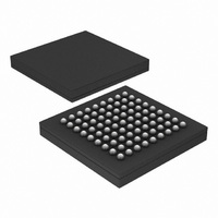
IC PCI-EXPRESS X1 PHY 81-LFBGA
Manufacturer
NXP Semiconductors
Specifications of PX1011BI-EL1/G,551
Package / Case
81-LFBGA
Applications
PCI Express MAX to PCI Express PHY
Interface
JTAG
Voltage - Supply
1.2 V
Mounting Type
Surface Mount
Input Voltage Range (max)
0.31 V
Maximum Operating Temperature
+ 85 C
Maximum Power Dissipation
300 mW
Minimum Operating Temperature
- 40 C
Mounting Style
SMD/SMT
Operating Supply Voltage
1.2 V
Supply Current (max)
28 mA
Lead Free Status / RoHS Status
Lead free / RoHS Compliant
Lead Free Status / RoHS Status
Lead free / RoHS Compliant, Lead free / RoHS Compliant
Other names
935282114551
PX1011BI-EL1/G-S
PX1011BI-EL1/G-S
PX1011BI-EL1/G-S
PX1011BI-EL1/G-S
Available stocks
Company
Part Number
Manufacturer
Quantity
Price
Company:

Part Number:
PX1011BI-EL1/G,551
Manufacturer:
NXP Semiconductors
Quantity:
10 000


NXP Semiconductors
Table 18.
PX1011B_4
Product data sheet
Symbol
dV/dt
V
V
Transmitter
UI
V
t
t
V
t
t
V
V
I
RL
RL
Z
C
t
t
t
t
t
TX_EYE_m-mJITTER
TX_JITTER_MAX
TX_RISE
TX_FALL
TX_SHORT
lock(PLL)
TX_latency
P0s_exit_latency
P1_exit_latency
RESET-PHYSTATUS
REFCLK
V
V
TX_DC
IH
IL
TX_DIFFp-p
TX_DE_RATIO
TX_CM_ACp
TX_CM_DC
TX
CM_DC_ACT_IDLE
CM_DC_LINE
TX_DIFF
TX_CM
PCI Express PHY characteristics
Parameter
rate of change of voltage
differential input HIGH voltage
differential input LOW voltage
duty cycle on pin REFCLK
unit interval
differential peak-to-peak output
voltage
maximum time between the jitter
median and maximum deviation from
the median
maximum transmitter jitter time
de-emphasized differential output
voltage ratio
D+/D TX output rise time
D+/D TX output fall time
RMS AC peak common mode output
voltage
absolute delta of DC common mode
voltage during L0 and electrical idle
absolute delta of DC common mode
voltage between D+ and D
TX DC common mode voltage
TX short-circuit current limit
differential return loss
common mode return loss
transmitter DC impedance
AC coupling capacitor
PLL lock time
transmitter latency
P0s state exit latency
P1 state exit latency
RESET_N HIGH to PHYSTATUS LOW
time
…continued
Rev. 04 — 4 September 2009
Conditions
at rising edge;
measured from 150 mV
to +150 mV on the
differential waveform;
Figure 17
at falling edge;
measured from +150 mV
to 150 mV on the
differential waveform;
Figure 17
on pin REFCLK_N and
pin REFCLK_P
1 clock cycle is 4 ns
PCI Express stand-alone X1 PHY
Min
0.6
0.6
+150
-
40
399.88 400
0.8
-
-
50
50
-
0
0
0
-
12
6
40
75
-
4
-
-
-
3.0
Typ
-
-
-
-
-
-
35
60
-
75
75
-
-
-
-
20
-
-
50
100
-
-
-
-
-
PX1011B
© NXP B.V. 2009. All rights reserved.
Max
4.0
4.0
-
60
400.12 ps
1.2
50
100
-
-
20
100
25
3.6
90
-
-
60
200
50
9
2.5
64
64
150
4.0
21 of 30
Unit
V/ns
V/ns
mV
mV
%
V
ps
ps
dB
ps
ps
mV
mV
mV
V
mA
dB
dB
nF
clock
cycle
s
s
s
s
Related parts for PX1011BI-EL1/G,551
Image
Part Number
Description
Manufacturer
Datasheet
Request
R

Part Number:
Description:
IC PCI-EXPRESS X1 PHY 81-LFBGA
Manufacturer:
NXP Semiconductors
Datasheet:

Part Number:
Description:
Telecom Line Management ICs PCI EXPRESS STAND ALONE X1 PHY
Manufacturer:
NXP Semiconductors
Part Number:
Description:
Telecom Line Management ICs PCI EXPRESS STAND ALONE X1 PHY
Manufacturer:
NXP Semiconductors
Part Number:
Description:
IC PCI-EXPRESS X1 PHY 81LFBGA
Manufacturer:
NXP Semiconductors
Datasheet:
Part Number:
Description:
Manufacturer:
NXP Semiconductors
Datasheet:
Part Number:
Description:
NXP Semiconductors designed the LPC2420/2460 microcontroller around a 16-bit/32-bitARM7TDMI-S CPU core with real-time debug interfaces that include both JTAG andembedded trace
Manufacturer:
NXP Semiconductors
Datasheet:

Part Number:
Description:
NXP Semiconductors designed the LPC2458 microcontroller around a 16-bit/32-bitARM7TDMI-S CPU core with real-time debug interfaces that include both JTAG andembedded trace
Manufacturer:
NXP Semiconductors
Datasheet:
Part Number:
Description:
NXP Semiconductors designed the LPC2468 microcontroller around a 16-bit/32-bitARM7TDMI-S CPU core with real-time debug interfaces that include both JTAG andembedded trace
Manufacturer:
NXP Semiconductors
Datasheet:
Part Number:
Description:
NXP Semiconductors designed the LPC2470 microcontroller, powered by theARM7TDMI-S core, to be a highly integrated microcontroller for a wide range ofapplications that require advanced communications and high quality graphic displays
Manufacturer:
NXP Semiconductors
Datasheet:
Part Number:
Description:
NXP Semiconductors designed the LPC2478 microcontroller, powered by theARM7TDMI-S core, to be a highly integrated microcontroller for a wide range ofapplications that require advanced communications and high quality graphic displays
Manufacturer:
NXP Semiconductors
Datasheet:
Part Number:
Description:
The Philips Semiconductors XA (eXtended Architecture) family of 16-bit single-chip microcontrollers is powerful enough to easily handle the requirements of high performance embedded applications, yet inexpensive enough to compete in the market for hi
Manufacturer:
NXP Semiconductors
Datasheet:
Part Number:
Description:
The XA-S3 device is a member of Philips Semiconductors? XA(eXtended Architecture) family of high performance 16-bitsingle-chip microcontrollers
Manufacturer:
NXP Semiconductors
Datasheet:

Part Number:
Description:
The NXP BlueStreak LH75401/LH75411 family consists of two low-cost 16/32-bit System-on-Chip (SoC) devices
Manufacturer:
NXP Semiconductors
Datasheet:
Part Number:
Description:
The NXP LPC3130/3131 combine an 180 MHz ARM926EJ-S CPU core, high-speed USB2
Manufacturer:
NXP Semiconductors
Datasheet: