ADM1024ARUZ ON Semiconductor, ADM1024ARUZ Datasheet - Page 8
ADM1024ARUZ
Manufacturer Part Number
ADM1024ARUZ
Description
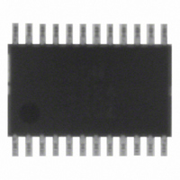
IC MONITOR SYS TEMP/VOLT 24TSSOP
Manufacturer
ON Semiconductor
Datasheet
1.ADM1024ARUZ.pdf
(29 pages)
Specifications of ADM1024ARUZ
Applications
PC's, PDA's
Interface
Serial
Voltage - Supply
2.8 V ~ 5.5 V
Package / Case
24-TSSOP
Mounting Type
Surface Mount
Temperature Sensor Function
Temp Sensor
Output Type
Digital
Package Type
TSSOP
Operating Temperature (min)
0C
Operating Temperature (max)
100C
Operating Temperature Classification
Commercial
Operating Supply Voltage (typ)
3.3V
Operating Supply Voltage (max)
5.5V
Full Temp Accuracy
+/- 2 C , +/- 3 C
Digital Output - Bus Interface
SMBus
Digital Output - Number Of Bits
10 bit
Supply Voltage (max)
12 V
Supply Voltage (min)
2.5 V
Maximum Operating Temperature
+ 100 C
Minimum Operating Temperature
0 C
Supply Current
1.4 mA
Lead Free Status / RoHS Status
Lead free / RoHS Compliant
Available stocks
Company
Part Number
Manufacturer
Quantity
Price

Part Number:
ADM1024ARUZ
Manufacturer:
ADI/亚德诺
Quantity:
20 000


General Description
microprocessor−based systems. The device communicates
with the system via a serial SMBus. The serial bus controller
has a hardwired address line for device selection (Pin 1), a
serial data line for reading and writing addresses and data
(SDA, Pin 14), and an input line for the serial clock (Pin 3),
and an input line for the serial clock (Pin 4). All control and
programming functions of the ADM1024 are performed over
the serial bus.
Measurement Inputs
ADM1024 extremely flexible and versatile. The device has
a 10−bit ADC and nine measurement input pins that can be
configured in different ways.
analog inputs with a range of 0 V to 2.5 V, or as digital inputs
to monitor the speed of fans with digital tachometer outputs.
The fan inputs can be programmed to accommodate fans
with different speeds and different numbers of pulses per
revolution from their tachometer outputs.
be connected to the cathode and anode of an external
temperature sensing diode.
on−chip attenuators, configured to monitor 12 V, 5.0 V, and
the processor core voltage, respectively.
on−chip attenuators to monitor a second processor core voltage
and a 2.5 V supply, or they may be configured as a temperature
input and connected to a second temperature−sensing diode.
temperature sensor that monitors system−ambient temperature.
is powered, so there is no need for a separate 3.3 V analog
input if the chip V
measurement can be configured for either a 3.3 V or 5.0 V
V
Sequential Measurement
cycles sequentially through the measurement of analog
inputs and the temperature sensor, while at the same time the
fan speed inputs are independently monitored. Measured
values from these inputs are stored in Value Registers. These
can be read out over the serial bus, or can be compared with
programmed limits stored in the Limit Registers. The results
of out−of−limit comparisons are stored in the Interrupt
Status Registers, and will generate an interrupt on the INT
line (Pin 10).
appropriate programming of the Interrupt Mask Register.
CC
The ADM1024 is a complete system hardware monitor for
Programmability of the measurement inputs makes the
Pins 5 and 6 can be programmed as general−purpose
Pins 13 and 14 are dedicated temperature inputs and may
Pins 15, 16, and 19 are dedicated analog inputs with
Pins 17 and 18 may be configured as analog inputs with
The ADC also accepts input from an on−chip band gap
Finally, the ADM1024 monitors the supply from which it
When the ADM1024 monitoring sequence is started, it
Any or all of the Interrupt Status Bits can be masked by
by Bit 3 of the Channel Mode Register.
CC
is 3.3 V. The range of this V
http://onsemi.com
CC
8
Processor Voltage ID
the processor voltage ID code. These inputs can also be
reconfigured as interrupt inputs.
Chassis Intrusion
unauthorized tampering with the equipment.
RESET
pin low will reset all ADM1024 internal registers to default
values. The ADM1024 can also be programmed to give a
low going 45 ms reset pulse at this pin.
Analog Output
output range of 0 V to 2.5 V (Pin 11). This is typically used
to implement a temperature−controlled fan by controlling
the speed of a fan dependent upon the temperature measured
by the on−chip temperature sensor.
providing a NAND tree test function. The AOUT (Pin 11)
also doubles as a NAND test input, while Pin 1 doubles as
a NAND tree output.
Internal Registers of the ADM1024
registers follows. More detailed information on the function
of each register is given in Table 6 to Table 19:
Five digital inputs (VID4 to VID0—Pins 20 to 24) read
The VID pins have internal 100 kW pullup resistors.
A chassis intrusion input (Pin 7) is provided to detect
A RESET input/output (Pin 12) is provided. Pulling this
The ADM1024 contains an on−chip, 8−bit DAC with an
Testing of board level connectivity is simplified by
A brief description of the ADM1024’s principal internal
♦
♦
♦
♦
♦
♦
♦
configuration.
operating modes of the input channels.
address that selects one of the other internal
registers. When writing to the ADM1024, the first
byte of data is always a register address, which is
written to the Address Pointer Register.
provide status of each interrupt event. These registers
are also mirrored at addresses 4Ch and 4Dh.
individual interrupt sources.
configuration of the temperature interrupt is
controlled by the lower three bits of this register.
VID4 pins of the processor can be written to and
read from these registers. Divisor values for fan
speed measurement are also stored in this register.
Interrupt (INT) Status Registers: Two registers to
Configuration Registers: Provide control and
Channel Mode Register: Stores the data for the
Address Pointer Register: This register contains the
Interrupt (INT) Mask Registers: Allow masking of
Temperature Configuration Register: The
VID/Fan Divisor Register: The status of the VID0 to
Related parts for ADM1024ARUZ
Image
Part Number
Description
Manufacturer
Datasheet
Request
R


Part Number:
Description:
ON Semiconductor [VOLTAGE REGULATOR]
Manufacturer:
ON Semiconductor
Datasheet:
Part Number:
Description:
357-036-542-201 CARDEDGE 36POS DL .156 BLK LOPRO
Manufacturer:
ON Semiconductor
Datasheet:
Part Number:
Description:
357-036-542-201 CARDEDGE 36POS DL .156 BLK LOPRO
Manufacturer:
ON Semiconductor
Datasheet:
Part Number:
Description:
357-036-542-201 CARDEDGE 36POS DL .156 BLK LOPRO
Manufacturer:
ON Semiconductor
Datasheet:
Part Number:
Description:
357-036-542-201 CARDEDGE 36POS DL .156 BLK LOPRO
Manufacturer:
ON Semiconductor
Datasheet:
Part Number:
Description:
357-036-542-201 CARDEDGE 36POS DL .156 BLK LOPRO
Manufacturer:
ON Semiconductor
Datasheet:
Part Number:
Description:
357-036-542-201 CARDEDGE 36POS DL .156 BLK LOPRO
Manufacturer:
ON Semiconductor
Datasheet:
Part Number:
Description:
357-036-542-201 CARDEDGE 36POS DL .156 BLK LOPRO
Manufacturer:
ON Semiconductor
Datasheet:
Part Number:
Description:
357-036-542-201 CARDEDGE 36POS DL .156 BLK LOPRO
Manufacturer:
ON Semiconductor
Datasheet:
Part Number:
Description:
357-036-542-201 CARDEDGE 36POS DL .156 BLK LOPRO
Manufacturer:
ON Semiconductor
Datasheet:
Part Number:
Description:
357-036-542-201 CARDEDGE 36POS DL .156 BLK LOPRO
Manufacturer:
ON Semiconductor
Datasheet:
Part Number:
Description:
Manufacturer:
ON Semiconductor
Datasheet:
Part Number:
Description:
Manufacturer:
ON Semiconductor
Datasheet: