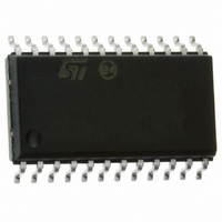
STLED316SMTR STMicroelectronics, STLED316SMTR Datasheet - Page 17

STLED316SMTR
Manufacturer Part Number
STLED316SMTR
Description
IC LED CTLR SERIAL 6DIGIT SO-24
Manufacturer
STMicroelectronics
Datasheet
1.STLED316SMTR.pdf
(33 pages)
Specifications of STLED316SMTR
Applications
LED Controller with Keyscan, 6-Digit
Interface
Serial
Voltage - Supply
4.5 V ~ 5.5 V
Package / Case
24-SOIC (7.5mm Width)
Mounting Type
Surface Mount
Number Of Digits
6
Number Of Segments
48
Operating Supply Voltage
4.5 V to 5.5 V
Maximum Supply Current
15000 uA
Maximum Power Dissipation
1200 mW
Maximum Operating Temperature
+ 85 C
Mounting Style
SMD/SMT
Minimum Operating Temperature
- 40 C
For Use With
497-8417 - BOARD DEMO FRONT PANEL STLED316S497-8399 - BOARD EVAL ST7LITE49M/STLED316S497-8432 - BOARD LED CTLR/DVR STLED316S
Lead Free Status / RoHS Status
Lead free / RoHS Compliant
Other names
497-6925-2
STLED316SMTR
STLED316SMTR
Available stocks
Company
Part Number
Manufacturer
Quantity
Price
Company:
Part Number:
STLED316SMTR
Manufacturer:
TE
Quantity:
17 600
Part Number:
STLED316SMTR
Manufacturer:
ST
Quantity:
20 000
Company:
Part Number:
STLED316SMTR#Y4
Manufacturer:
MICROCHIP
Quantity:
1 430
STLED316S
6
Key-scan & display cycle
The display RAM stores the data transmitted from an external device to the STLED316S
through the serial interface. Refer to
for a pictorial representation.
The grid and segment outputs are controlled by the display output module. The entire grid
will be turned off on channel 1/16 and 16/16 meaning that the first channel and last channel
are off. This is referred to as blanking time.
During the keyscan time (first cycle from timing generator), the entire grid is turned off and
only the segments are enabled one by one (seg0 to seg7). The segment on time is 64 µs.
During the LED discrete time (second cycle), the data present on the internal LED buffer is
checked. If the data is present, then the brightness setting of each LED in the brightness
control register is checked. Then each segment will be enabled or disabled based on the
register value. In this duration, the grids 1 to 6 are turned off. The grid corresponding to LED
digit is turned on. The LED on duty cycle is 14/16. If the LED/seg1 brightness is 12/16, it
means that the segment1 OFF time is 12/16 and on time is 2/16.
During 7-segment display time (3
it is ON or OFF. If display is ON, then the dimming settings are checked from the
configuration register for the grid (it may be common dimming setting or individual dimming
setting for each digit). The minimum turn on time is 1/16 and maximum turn on time is 14/16.
The blanking time is valid before the turning on and turning off of the grid. The blanking
interval is 32 µs. This will continue until the maximum number of digits configured in the
register. Once the full cycle is complete, the keyscan cycle will start again.
If the display is not turned on, then the timing generation will immediately go to the key scan
mode.
Initial:
All the segments and grids are turned off.
During operation:
1.
2.
3.
Turn on segment (keyscan) one by one. On time duration is 64 µs.
Check the data present in LED register. If data is present, turn on the respective LED
grid and segments.
Check the display on. If display is turned on, then enable the grid one by one from grid
1 to grid 6 (maximum) and turn on segments.
rd
cycle to 8
Section 9: Key-scanning and display timing on page 25
th
cycle), the display status is checked whether
Key-scan & display cycle
17/33


