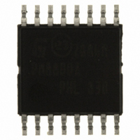
PM8800ATR STMicroelectronics, PM8800ATR Datasheet - Page 6

PM8800ATR
Manufacturer Part Number
PM8800ATR
Description
IC POE-PD PWM CTLR 16-HTSSOP
Manufacturer
STMicroelectronics
Datasheet
1.PM8800ATR.pdf
(35 pages)
Specifications of PM8800ATR
Applications
Power Over Ethernet (PoE)
Interface
IEEE 802.3af
Voltage - Supply
10 V
Package / Case
16-TSSOP Exposed Pad, 16-eTSSOP, 16-HTSSOP
Mounting Type
Surface Mount
For Use With
497-6366 - BOARD EVAL FOR PM8800A
Lead Free Status / RoHS Status
Lead free / RoHS Compliant
Other names
497-6897-2
PM8800ATR
PM8800ATR
Available stocks
Company
Part Number
Manufacturer
Quantity
Price
Company:
Part Number:
PM8800ATR
Manufacturer:
ON
Quantity:
300 000
Part Number:
PM8800ATR
Manufacturer:
ST
Quantity:
20 000
Pins description and connection diagrams
2
2.1
6/35
Pins description and connection diagrams
Figure 5.
Pin descriptions
Table 2.
Pin#
1
2
3
4
5
6
AUXI_IRL
RCLASS
Name
AUXII
VIN
RT
SS
Pins connection (top view)
Pin description
AUXI_IRL
Oscillator timing resistor pin and synchronization input.
An external resistor connected from RT to AGND sets the oscillator frequency.
This pin will also accept narrow ac-coupled synchronization pulses from an
external clock.
Soft-start input.
An external capacitor connected from SS and AGND and an internal
10 µA current source set the soft-start ramp rate. this pin is also used to set the
hiccup timer in case of overcurrent conditions. See
Auxiliary source enable pin.
Use this pin to power up the DC/DC section only from the external source. The
auxiliary source can prevail over the PoE source depending on the value of the
resistor between this pin and the external source. See
System high potential input.
The diode “OR” of PoE line and auxiliary sources connected to the PD, it is the
most positive input potential.
Classification resistor pin.
Connect a classification programming resistor between this pin and VSS.
In-rush current limit and auxiliary source enable pin.
Pulling up this pin to the auxiliary source will change the internal UVLO settings
and allow PD to be powered with voltage lower than nominal PoE voltages. In this
condition inrush current limit is set to default values. See
A resistance between this pin and VSS will set the level of inrush current limit.
RCLASS
AUXII
DCCL
VSS
VIN
RT
SS
1
2
3
4
5
6
7
8
HTSSOP-16
Function
16
15
14
13
12
11
10
9
Section 6
AGND
VFB
COMP
CS
nPGD
VCC
GD
GND
Section 7
Section 7
for detail.
for detail.
for details.
PM8800A


