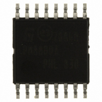
PM8800ATR STMicroelectronics, PM8800ATR Datasheet - Page 26

PM8800ATR
Manufacturer Part Number
PM8800ATR
Description
IC POE-PD PWM CTLR 16-HTSSOP
Manufacturer
STMicroelectronics
Datasheet
1.PM8800ATR.pdf
(35 pages)
Specifications of PM8800ATR
Applications
Power Over Ethernet (PoE)
Interface
IEEE 802.3af
Voltage - Supply
10 V
Package / Case
16-TSSOP Exposed Pad, 16-eTSSOP, 16-HTSSOP
Mounting Type
Surface Mount
For Use With
497-6366 - BOARD EVAL FOR PM8800A
Lead Free Status / RoHS Status
Lead free / RoHS Compliant
Other names
497-6897-2
PM8800ATR
PM8800ATR
Available stocks
Company
Part Number
Manufacturer
Quantity
Price
Company:
Part Number:
PM8800ATR
Manufacturer:
ON
Quantity:
300 000
Part Number:
PM8800ATR
Manufacturer:
ST
Quantity:
20 000
PWM section
6.4
6.5
26/35
PWM comparator / slope compensation
In typical isolated operation, current is sensed on a sense resistor Rs put between the
source of the primary side MOSFET and GND pin, while for non-isolated topology it is often
sensed on a proper resistor put on the source of a low-side MOSFET.
The PWM comparator produces the PWM duty cycle by comparing the Rs ramp signal on
CS with an error voltage derived from the error amplifier output.
The error amplifier output voltage at the COMP pin is offset by 0.7 V and then further
attenuated by a 2:1 resistor divider before it is presented to the PWM comparator input.
The PWM duty cycle increases with the voltage at the COMP pin. The controller output duty
cycle reduces to zero when the COMP pin voltage drops below approximately 0.7 V.
For duty cycles greater than 50 %, current mode control loops are subject to sub-harmonic
oscillation. The PM8800A fixes the maximum duty dycle at 80 % and implements a slope
compensation technique consisting on adding an additional fixed slope voltage ramp to the
signal at the CS pin. This is achieved by injecting a 45 µA sawtooth current into the current
sense signal path on an integrated 2 kΩ resistor.
Additional slope compensation may be added by increasing the source impedance of the
current sense signal with an external resistor between the CS pin and the source of the
current sense signal. The net effect in this case is to increase the slope of the voltage ramp
at the PWM comparator terminals.
Current limiting
The current sensed through the CS pin is compared to two fixed levels of 0.5 V and 0.7 V.
The lower level is used to perform a cycle-by-cycle current limit, terminating the PWM pulse.
In case of recurring overload a timing structure is activated through SS pin, sourcing a small
current of about 1 µA on SS capacitor. The voltage on SS rises whenever during a PWM
cycle an over current event occurs, while decreases to the default voltage (2.3 V) if it does
not.
If SS voltage reaches 2.8 V, a slow hiccup is performed sinking 1 µA from SS, and shutting
down the gate driver until the SS capacitor is fully discharged.
Then a new soft-start procedure is performed.
PM8800A


