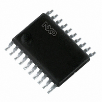
PCA9545BPW,118 NXP Semiconductors, PCA9545BPW,118 Datasheet - Page 9

PCA9545BPW,118
Manufacturer Part Number
PCA9545BPW,118
Description
IC I2C SWITCH 4CH 20-TSSOP
Manufacturer
NXP Semiconductors
Datasheet
1.PCA9545BPW118.pdf
(28 pages)
Specifications of PCA9545BPW,118
Package / Case
20-TSSOP
Applications
4-Channel I²C Switcher
Interface
I²C
Voltage - Supply
2.3 V ~ 3.6 V, 4.5 V ~ 5.5 V
Mounting Type
Surface Mount
Product
Multiplexer
Number Of Lines (input / Output)
4.0 / 1.0
Propagation Delay Time
0.3 ns at 2.3 V to 5.5 V
Supply Voltage (max)
5.5 V
Supply Voltage (min)
2.3 V
Maximum Operating Temperature
+ 85 C
Minimum Operating Temperature
- 40 C
Mounting Style
SMD/SMT
Number Of Input Lines
4.0
Number Of Output Lines
1.0
Logical Function
I2C Multiplexer
Configuration
1 x 4:1
Number Of Inputs
4
Number Of Outputs
1
Operating Supply Voltage (typ)
2.5/3.3/5V
Operating Supply Voltage (min)
2.3V
Operating Supply Voltage (max)
5.5V
Power Dissipation
400mW
Operating Temp Range
-40C to 85C
Operating Temperature Classification
Industrial
Mounting
Surface Mount
Pin Count
20
Package Type
TSSOP
Lead Free Status / RoHS Status
Lead free / RoHS Compliant
Lead Free Status / RoHS Status
Lead free / RoHS Compliant, Lead free / RoHS Compliant
Other names
568-4246-2
935283307118
PCA9545BPW-T
935283307118
PCA9545BPW-T
NXP Semiconductors
PCA9545A_45B_45C_7
Product data sheet
6.4 Power-on reset
6.5 Voltage translation
When power is applied to V
PCA9545A/45B/45C in a reset condition until V
reset condition is released and the PCA9545A/45B/45C registers and I
machine are initialized to their default states (all zeroes) causing all the channels to be
deselected. Thereafter, V
The pass gate transistors of the PCA9545A/45B/45C are constructed such that the V
voltage can be used to limit the maximum voltage that will be passed from one I
another.
Figure 9
was generated using the data specified in
sheet). In order for the PCA9545A/45B/45C to act as a voltage translator, the V
voltage should be equal to, or lower than the lowest bus voltage. For example, if the main
bus was running at 5 V, and the downstream buses were 3.3 V and 2.7 V, then V
should be equal to or below 2.7 V to effectively clamp the downstream bus voltages.
Looking at
supply voltage is 3.5 V or lower, so the PCA9545A/45B/45C supply voltage could be set to
3.3 V. Pull-up resistors can then be used to bring the bus voltages to their appropriate
levels (see
More Information can be found in Application Note AN262: PCA954X family of I
multiplexers and switches .
Fig 9.
(1) maximum
(2) typical
(3) minimum
shows the voltage characteristics of the pass gate transistors (note that the graph
Pass gate voltage versus supply voltage
Figure
Figure
9, we see that V
16).
V
o(sw)
(V)
Rev. 07 — 19 June 2009
5.0
4.0
3.0
2.0
1.0
DD
2.0
DD
must be lowered below 0.2 V to reset the device.
, an internal Power-On Reset (POR) holds the
2.5
4-channel I
o(sw)(max)
3.0
3.5
Section 10 “Static characteristics”
2
will be at 2.7 V when the PCA9545A/45B/45C
C-bus switch with interrupt logic and reset
4.0
DD
PCA9545A/45B/45C
(1)
(2)
(3)
has reached V
4.5
002aaa964
5.0
V
DD
(V)
5.5
POR
. At this point, the
2
© NXP B.V. 2009. All rights reserved.
C-bus state
of this data
2
o(sw)
2
C/SMBus
C-bus to
o(sw)
9 of 28
DD


