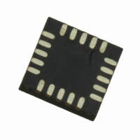
MPR121QR2 Freescale Semiconductor, MPR121QR2 Datasheet - Page 45

MPR121QR2
Manufacturer Part Number
MPR121QR2
Description
IC CTLR TOUCH SENSOR 20-QFN
Manufacturer
Freescale Semiconductor
Type
Capacitive, Proximity Sensorr
Datasheet
1.MPR121QR2.pdf
(57 pages)
Specifications of MPR121QR2
Number Of Inputs/keys
12 Key
Data Interface
I²C, Serial
Voltage - Supply
1.71 V ~ 3.6 V
Current - Supply
29µA
Operating Temperature
-40°C ~ 85°C
Mounting Type
Surface Mount
Package / Case
20-UQFN, 20-µQFN
Output Type
Logic
Interface
I²C
Input Type
Logic
Supply Voltage
2.5 V to 3.6 V
Dimensions
3 mm L x 3 mm W x 0.65 mm H
Temperature Range
- 40 C to + 85 C
Termination Style
SMD/SMT
Supply Current
29µA
Ic Interface Type
I2C
Supply Voltage Range
1.71V To 3.6V
Sensor Case Style
QFN
No. Of Pins
20
Operating Temperature Range
-40°C To +85°C
Interface Type
I2C
Rohs Compliant
Yes
Lead Free Status / RoHS Status
Lead free / RoHS Compliant
Other names
MPR121QR2
MPR121QR2TR
MPR121QR2TR
Available stocks
Company
Part Number
Manufacturer
Quantity
Price
Part Number:
MPR121QR2
Manufacturer:
FREESCALE
Quantity:
20 000
Sensors
Freescale Semiconductor
enabled and the function is configured by CTL0, CTL1 and DIR bits. When the port is used as input, it can be configured as normal
input or with additional internal pull-down or pull-up for input port. For output configuration, it can be push/pull or open drain.
DAT[7:0]: Data Register
charging and AD conversion and the level transition will be occurred after the AD conversion. Reading this register returns the
content of the DAT register (not a level of the port).
register). A write changes content of the register, but not affect to the input function.
SET[7:0]: Set Data Register
CLR[7:0]: Clear Data Register
TOG[7:0]: Toggle Data Register
tents of the corresponding DAT bit. Write “0” has no meaning. Using of those registers allows any individual port(s) to be able
individually set, cleared, or toggled without affecting other ports. Reading those register returns as same as DAT register reading.
LED DRIVER
output to an LED forward biased with its cathode to GND so that GPIO output high lights the LED. Place a current limiting resistor
is series with LED to limit the current below 12 mA (refer to the typical application circuit).
the PWM can also be used to drive the beeper.
Table 45. PWM_[3:0}: PWM Duty Control Registers
PWM 0
PWM 1
PWM 2
PWM 3
Name
The GPIO system allows the GPIO pins to be set as input or output. When an EN bit sets, the corresponding GPIO pin is
When a GPIO is as output, the GPIO port outputs the bit level of this register. The output level toggle holds on any electrode
When a GPIO is as input, reading this register returns latched input level of the corresponding port (not contents of the DAT
Writing a “1” to bits in this register will set them in the Data Register.
Writing a “1” to bits in this register will clear them in the Data Register.
Write a bit with “1” to the GPIO Data Set Register, GPIO Data Clear Register, and GPIO Toggle Register set/clear/toggle con-
Each GPIO pin has LED driver capability which can source up to 12 mA. When GPIO is used to driver LED, connect the GPIO
When LED dimming control is needed, the PWM control register can be set to get the desired dimming control. Alternatively,
Address
EN
0
1
1
1
1
1
1
1
1
0x81
0x82
0x83
0x84
DIR
X
0
0
0
0
1
1
1
1
PWM1[3]
PWM3[3]
PWM5[3]
PWM7[3]
D7
CTL[0:1]
XX
00
10
11
01
00
11
10
01
PWM1[2]
PWM3[2]
PWM5[2]
PWM7[2]
D6
GPIO function is disabled. Port is high-z state.
GPIO port becomes input port.
GPIO port becomes input port with internal pull-down.
GPIO port becomes input port with internal pull-up.
Not defined yet (as same as CTL = 00).
GPIO port becomes CMOS output port.
GPIO port becomes high side only open drain output port for LED driver.
GPIO port becomes low side only open drain output port.
Not defined yet (as same as CTL = 00).
PWM1[1]
PWM3[1]
PWM5[1]
PWM7[1]
D5
PWM1[0]
PWM3[0]
PWM5[0]
PWM7[0]
D4
DESCRIPTION
PWM0[3]
PWM2[3]
PWM4[3]
PWM6[3]
D3
PWM0[2]
PWM2[2]
PWM4[2]
PWM6[2]
D2
PWM0[1]
PWM2[1]
PWM4[1]
PWM6[1]
D1
PWM0[0]
PWM2[0]
PWM4[0]
PWM6[0]
MPR121
D0
45


