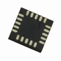
MPR121QR2 Freescale Semiconductor, MPR121QR2 Datasheet - Page 15

MPR121QR2
Manufacturer Part Number
MPR121QR2
Description
IC CTLR TOUCH SENSOR 20-QFN
Manufacturer
Freescale Semiconductor
Type
Capacitive, Proximity Sensorr
Datasheet
1.MPR121QR2.pdf
(57 pages)
Specifications of MPR121QR2
Number Of Inputs/keys
12 Key
Data Interface
I²C, Serial
Voltage - Supply
1.71 V ~ 3.6 V
Current - Supply
29µA
Operating Temperature
-40°C ~ 85°C
Mounting Type
Surface Mount
Package / Case
20-UQFN, 20-µQFN
Output Type
Logic
Interface
I²C
Input Type
Logic
Supply Voltage
2.5 V to 3.6 V
Dimensions
3 mm L x 3 mm W x 0.65 mm H
Temperature Range
- 40 C to + 85 C
Termination Style
SMD/SMT
Supply Current
29µA
Ic Interface Type
I2C
Supply Voltage Range
1.71V To 3.6V
Sensor Case Style
QFN
No. Of Pins
20
Operating Temperature Range
-40°C To +85°C
Interface Type
I2C
Rohs Compliant
Yes
Lead Free Status / RoHS Status
Lead free / RoHS Compliant
Other names
MPR121QR2
MPR121QR2TR
MPR121QR2TR
Available stocks
Company
Part Number
Manufacturer
Quantity
Price
Part Number:
MPR121QR2
Manufacturer:
FREESCALE
Quantity:
20 000
Sensors
Freescale Semiconductor
FILTER CONFIGURATION REGISTER
electrodes can also be independently configured.
ELECTRODE CHARGE CURRENT REGISTER
The SFI, ESI and FFI are described in AN3890. In addition to these global (same for all electrodes) settings, the MPR121
Table 10. Filter Configuration Register Field Descriptions
Table 11. Electrode Charge Current Register Field Descriptions
Reset:
Reset:
Field
Field
CDC
CDT
ESI
SFI
7:5
4:3
2:0
5:0
W
W
R
R
7
0
7
0
0
= Unimplemented
= Unimplemented
Charge Discharge Time – The Charge Discharge Time field selects the amount of
time an electrode charges and discharges.
000 Encoding 0 – Invalid
001 Encoding 1 – Time is set to 0.5 μs
010 Encoding 2 – Time is set to 1 μs
~
111 Encoding 7 – Time is set to 32 μs.
Second Filter Iterations – The Second Filter Iterations field selects the number of
samples taken for the second level filter.
00 Encoding 0 – Number of samples is set to 4
01 Encoding 1 – Number of samples is set to 6
10 Encoding 2 – Number of samples is set to 10
11 Encoding 3 – Number of samples is set to 18
Electrode Sample Interval – The Electrode Sample Interval field selects the period
between samples used for the second level of filtering.
000 Encoding 0 – Period set to 1 ms
001 Encoding 1 – Period set to 2 ms
~
111 Encoding 7 – Period set to 128 ms
Electrode # Charge Discharge Current – The Charge Discharge Current field
selects the supply current to be used when charging and discharging an electrode.
000000 Encoding 0 – Disables Electrode Charging
000001 Encoding 1 – Sets the current to 1μA
~
111111 Encoding 63 – Sets the current to 63 μA
CDT
Figure 10. Electrode Charge Current Register
6
0
6
0
0
Figure 9. Filter Configuration Register
5
0
5
0
4
0
4
0
SFI
Description
Description
3
0
3
0
CDC
2
0
2
0
ESI
1
0
1
0
0
0
0
0
MPR121
15


