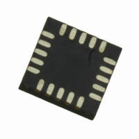
MPR121QR2 Freescale Semiconductor, MPR121QR2 Datasheet - Page 16

MPR121QR2
Manufacturer Part Number
MPR121QR2
Description
IC CTLR TOUCH SENSOR 20-QFN
Manufacturer
Freescale Semiconductor
Type
Capacitive, Proximity Sensorr
Datasheet
1.MPR121QR2.pdf
(57 pages)
Specifications of MPR121QR2
Number Of Inputs/keys
12 Key
Data Interface
I²C, Serial
Voltage - Supply
1.71 V ~ 3.6 V
Current - Supply
29µA
Operating Temperature
-40°C ~ 85°C
Mounting Type
Surface Mount
Package / Case
20-UQFN, 20-µQFN
Output Type
Logic
Interface
I²C
Input Type
Logic
Supply Voltage
2.5 V to 3.6 V
Dimensions
3 mm L x 3 mm W x 0.65 mm H
Temperature Range
- 40 C to + 85 C
Termination Style
SMD/SMT
Supply Current
29µA
Ic Interface Type
I2C
Supply Voltage Range
1.71V To 3.6V
Sensor Case Style
QFN
No. Of Pins
20
Operating Temperature Range
-40°C To +85°C
Interface Type
I2C
Rohs Compliant
Yes
Lead Free Status / RoHS Status
Lead free / RoHS Compliant
Other names
MPR121QR2
MPR121QR2TR
MPR121QR2TR
Available stocks
Company
Part Number
Manufacturer
Quantity
Price
Part Number:
MPR121QR2
Manufacturer:
FREESCALE
Quantity:
20 000
MPR121
16
ELECTRODE CHARGE TIME
AUTO-CONFIGURATION
the Charge Current the Charge Time. This eliminates much of the guess involved with touch sensors and allows the same set-
tings to properly configure the device for a wide range of application and electrodes. As show earlier in this document, the sen-
sitivity of the sensor is maximized by having the baseline be as high as possible for a specific baseline capacitance. The
restriction on the high side is that a system should not charge above V
target voltage used is approximately V
3.0 V. The following three registers should be set based on the V
assuming the lowest voltage necessary for the battery. If the final voltage supply in the system is not known, just use the 1.8 V
values as they represent the worst case. This lower setting will not dramatically affect the performance, thus the 1.8 V could be
considered default and be used in all cases where fine tuning is not required.
One of the new features added in the MPR121 that was not included in the MPR03X is the ability to automatically configure
This implies that the automatic configuration system should target approximately 156 when V
Table 12. Electrode Charge Time Register Field Descriptions
Reset:
CDT#
CDT#
Field
6:4
2:0
W
R
7
0
0
= Unimplemented
Table 13.
Voltage (V
Electrode # Charge Discharge Time – The Charge Discharge Time field selects the
amount of time an electrode charges and discharges.
000 Encoding 0 – Global value is used.
001 Encoding 1 – Time is set to 0.5 μs
010 Encoding 2 – Time is set to 1 μs
~
11 Encoding 7 – Time is set to 32 μs.
Electrode # Charge Discharge Time – The Charge Discharge Time field selects the
amount of time an electrode charges and discharges.
000 Encoding 0 – Global value is used.
001 Encoding 1 – Time is set to 0.5 μs
010 Encoding 2 – Time is set to 1 μs
~
11 Encoding 7 – Time is set to 32 μs.
DD
6
0
1.8 V
- 0.7 V.
Figure 11. Electric Charge Time Register
V
DD
DD
CDT#
)
5
0
V
DD
1.1 V
2.3 V
- 0.7 V
4
0
DD
in the system. If the voltage is unregulated, set the values
DD
Description
ADC
625
785
- 0.7 V due to this being a non-linear region. Thus the
3
0
0
Baseline
156
196
2
0
CDT#
DD
1
0
is 1.8 V and 196 when V
Freescale Semiconductor
0
0
Sensors
DD
is


