AT42QT1040-MMH Atmel, AT42QT1040-MMH Datasheet - Page 47
AT42QT1040-MMH
Manufacturer Part Number
AT42QT1040-MMH
Description
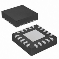
IC TOUCH SENSOR 4KEY 20-VQFN
Manufacturer
Atmel
Series
QTouch™r
Type
Resistiver
Specifications of AT42QT1040-MMH
Touch Panel Interface
4, 2-Wire
Number Of Inputs/keys
4 Key
Data Interface
I²C, Serial
Data Rate/sampling Rate (sps, Bps)
200k
Voltage Reference
Internal
Voltage - Supply
1.8 V ~ 5.5 V
Current - Supply
10mA
Operating Temperature
-40°C ~ 85°C
Mounting Type
Surface Mount
Package / Case
20-VQFN Exposed Pad, 20-HVQFN, 20-SQFN, 20-DHVQFN
Output Type
Logic
Input Type
Logic
Supply Voltage
1.8 V to 5.5 V
Dimensions
3 mm L x 3 mm W x 0.8 mm H
Output Voltage
0.7 V to 0.8 V
Temperature Range
- 40 C to + 85 C
Termination Style
SMD/SMT
Lead Free Status / RoHS Status
Lead free / RoHS Compliant
Interface
-
Lead Free Status / Rohs Status
Lead free / RoHS Compliant
Other names
AT42QT1040-MMH
AT42QT1040-MMHTR
AT42QT1040-MMHTR
Available stocks
Company
Part Number
Manufacturer
Quantity
Price
Company:

Part Number:
AT42QT1040-MMH
Manufacturer:
FUJITSU
Quantity:
349
Company:
Part Number:
AT42QT1040-MMH
Manufacturer:
Atmel
Quantity:
30 294
Part Number:
AT42QT1040-MMH
Manufacturer:
MICROCHIP/微芯
Quantity:
20 000
Part Number:
AT42QT1040-MMH-T
Manufacturer:
MICROCHIP/微芯
Quantity:
20 000
Part Number:
AT42QT1040-MMHR
Manufacturer:
ATMEL/爱特梅尔
Quantity:
20 000


5.1
5.2
5.2.1
5.2.2
Touch Sensors Design Guide
Introduction
General Advice
Ground Loading
Interconnection
This section describes how you design one-dimensional sensors using a self-capacitance
implementation (see
implement sliders or wheels for use with QTouch sensor controllers. Note that three active channels are
used in all the cases described in this section.
This type of sensor is normally only used with planar type construction methods. For construction ideas
see
Method” on page
Two types of sensor can be considered:
This section discusses both types of sensors.
One of the most important things to keep in mind with sliders and wheels is that they work best when
they have well-balanced sensitivities across all channels. Avoid ground loading underneath sliders and
wheels, as uneven or excessive ground loading underneath the sensors will render them useless.
Moderate or even ground loading may work, but the resolution of the output is reduced.
Generally speaking, avoid running any foreign traces or components underneath slider or wheel
sensors.
The following guidlines should be followed when designing the traces for slider and wheel sensors:
Spatially interpolated
This type uses the shape of the electrodes to spatially interpolate the electric fields above the sensor.
Resistively interpolated
This type uses physical resistors to electrically interpolate the electrodes. This type of sensor allows
for a simpler electrode design. It also allows larger sensors to be constructed.
Always run all three channel connections together as a group and keep them well away from noisy
sources and ground loads.
Keep the traces as short and thin as possible and space the traces with a gap equal to the track width.
When routing traces from the electrodes, use a via, if possible, for each electrode to route the traces
down to the non-touch side of the board, and then run the traces away on this layer.
Section 3.3.1 “Printed Electrode Method” on page 3-8
3-10.
Self-capacitance One-dimensional Sensors
Section 1.2
and
Section
1.3). These styles of sensors are typically used to
and
Section 3.3.3 “Secondary Substrate
Section 5
10620D–AT42–04/09
5-1
Related parts for AT42QT1040-MMH
Image
Part Number
Description
Manufacturer
Datasheet
Request
R

Part Number:
Description:
DEV KIT FOR AVR/AVR32
Manufacturer:
Atmel
Datasheet:

Part Number:
Description:
INTERVAL AND WIPE/WASH WIPER CONTROL IC WITH DELAY
Manufacturer:
ATMEL Corporation
Datasheet:
Part Number:
Description:
Low-Voltage Voice-Switched IC for Hands-Free Operation
Manufacturer:
ATMEL Corporation
Datasheet:
Part Number:
Description:
MONOLITHIC INTEGRATED FEATUREPHONE CIRCUIT
Manufacturer:
ATMEL Corporation
Datasheet:
Part Number:
Description:
AM-FM Receiver IC U4255BM-M
Manufacturer:
ATMEL Corporation
Datasheet:
Part Number:
Description:
Monolithic Integrated Feature Phone Circuit
Manufacturer:
ATMEL Corporation
Datasheet:
Part Number:
Description:
Multistandard Video-IF and Quasi Parallel Sound Processing
Manufacturer:
ATMEL Corporation
Datasheet:
Part Number:
Description:
High-performance EE PLD
Manufacturer:
ATMEL Corporation
Datasheet:
Part Number:
Description:
8-bit Flash Microcontroller
Manufacturer:
ATMEL Corporation
Datasheet:
Part Number:
Description:
2-Wire Serial EEPROM
Manufacturer:
ATMEL Corporation
Datasheet: