AT42QT1040-MMH Atmel, AT42QT1040-MMH Datasheet - Page 11
AT42QT1040-MMH
Manufacturer Part Number
AT42QT1040-MMH
Description
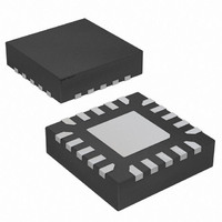
IC TOUCH SENSOR 4KEY 20-VQFN
Manufacturer
Atmel
Series
QTouch™r
Type
Resistiver
Specifications of AT42QT1040-MMH
Touch Panel Interface
4, 2-Wire
Number Of Inputs/keys
4 Key
Data Interface
I²C, Serial
Data Rate/sampling Rate (sps, Bps)
200k
Voltage Reference
Internal
Voltage - Supply
1.8 V ~ 5.5 V
Current - Supply
10mA
Operating Temperature
-40°C ~ 85°C
Mounting Type
Surface Mount
Package / Case
20-VQFN Exposed Pad, 20-HVQFN, 20-SQFN, 20-DHVQFN
Output Type
Logic
Input Type
Logic
Supply Voltage
1.8 V to 5.5 V
Dimensions
3 mm L x 3 mm W x 0.8 mm H
Output Voltage
0.7 V to 0.8 V
Temperature Range
- 40 C to + 85 C
Termination Style
SMD/SMT
Lead Free Status / RoHS Status
Lead free / RoHS Compliant
Interface
-
Lead Free Status / Rohs Status
Lead free / RoHS Compliant
Other names
AT42QT1040-MMH
AT42QT1040-MMHTR
AT42QT1040-MMHTR
Available stocks
Company
Part Number
Manufacturer
Quantity
Price
Company:

Part Number:
AT42QT1040-MMH
Manufacturer:
FUJITSU
Quantity:
349
Company:
Part Number:
AT42QT1040-MMH
Manufacturer:
Atmel
Quantity:
30 294
Part Number:
AT42QT1040-MMH
Manufacturer:
MICROCHIP/微芯
Quantity:
20 000
Part Number:
AT42QT1040-MMH-T
Manufacturer:
MICROCHIP/微芯
Quantity:
20 000
Part Number:
AT42QT1040-MMHR
Manufacturer:
ATMEL/爱特梅尔
Quantity:
20 000


2.1
Touch Sensors Design Guide
Charge Transfer
Atmel’s capacitive sensors work on a principle called charge transfer. This uses a switched capacitor
technique to assess relative changes in a sensor’s capacitance as it is touched.
Charge transfer works by applying a voltage pulse to series connection of the unknown capacitance Cx
and a charge integrator capacitor Cs. By repeating the pulse multiple times, a high resolution
measurement system is realized that can detect changes in capacitance of just a few femtofarads
In order to obtain stable and repeatable results, it is important that the voltage pulse is allowed to settle
properly and hence transfer all the charge into Cx and Cs (see
Because Cx and Cs are normally connected with some amount of series resistance, the RC time
constants so formed will tend to slow down this settling process.
It is therefore important that when designing a capacitive touch system that the amount of series
resistance is kept in mind in combination with the size of Cx (the sensor’s capacitance).
Series resistance is normally deliberately introduced to improve electromagnetic interference (EMI) and
ESD behavior (see the device datasheets for recommended series resistors). For some designs,
significant extra resistance can be introduced because of the resistivity of the tracks connecting the
sensor, or the resitivity of the electrode material itself. This is normally only true for designs using
material like Indium Tin Oxide (ITO), Orgacon
situations where adding deliberate extra series resistance can be beneficial, most notably in designs with
difficult ESD conditions or where emissions must be controlled to very low levels. A 10 k series resistor
can be a good choice. In either case, RC time constants can degrade the charge-transfer process so
some precautions must be taken.
For all designs, it is good practice to measure the settling time of the charge-transfer pulses to make
sure they are fast enough to work reliably. This can be done by observing the pulses using an
oscilloscope and coupling the scope probe to the sensor electrode capacitively
top of the overlying panel, or using a small piece of copper tape instead (see
The charge pulses should have substantially flat tops, that is the voltage has settled before the pulse
ends (see
1. One femtofarad is 1/1000 of a picofarad.
2. Orgacon™ is a trademark of Agfa-Gevaert Group. Orgacon is a printable conductive ink using a PEDOT polymer
3. Probing the sensor directly will add the capacitance of the probe and so give an unrealistic wave shape.
base. Care should be taken when assessing this material’s suitability for sensor construction due to the high
starting resistivity and the fact that this resistivity is known to increase over life depending on its exposure to UV,
heat and moisture (and any other oxidising substance). Consult Agfa before making any design decisions.
Figure 2-2 on page
2-2).
™ (2)
or Carbon with high /sq values. However, there are
Figure 2-2 on page
General Advice
Figure 2-1 on page
(3)
using a small coin on
2-2).
Section 2
10620D–AT42–04/09
(1)
2-2).
.
2-1
Related parts for AT42QT1040-MMH
Image
Part Number
Description
Manufacturer
Datasheet
Request
R

Part Number:
Description:
DEV KIT FOR AVR/AVR32
Manufacturer:
Atmel
Datasheet:

Part Number:
Description:
INTERVAL AND WIPE/WASH WIPER CONTROL IC WITH DELAY
Manufacturer:
ATMEL Corporation
Datasheet:
Part Number:
Description:
Low-Voltage Voice-Switched IC for Hands-Free Operation
Manufacturer:
ATMEL Corporation
Datasheet:
Part Number:
Description:
MONOLITHIC INTEGRATED FEATUREPHONE CIRCUIT
Manufacturer:
ATMEL Corporation
Datasheet:
Part Number:
Description:
AM-FM Receiver IC U4255BM-M
Manufacturer:
ATMEL Corporation
Datasheet:
Part Number:
Description:
Monolithic Integrated Feature Phone Circuit
Manufacturer:
ATMEL Corporation
Datasheet:
Part Number:
Description:
Multistandard Video-IF and Quasi Parallel Sound Processing
Manufacturer:
ATMEL Corporation
Datasheet:
Part Number:
Description:
High-performance EE PLD
Manufacturer:
ATMEL Corporation
Datasheet:
Part Number:
Description:
8-bit Flash Microcontroller
Manufacturer:
ATMEL Corporation
Datasheet:
Part Number:
Description:
2-Wire Serial EEPROM
Manufacturer:
ATMEL Corporation
Datasheet: