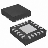
AT42QT1040-MMH Atmel, AT42QT1040-MMH Datasheet - Page 14

AT42QT1040-MMH
Manufacturer Part Number
AT42QT1040-MMH
Description
IC TOUCH SENSOR 4KEY 20-VQFN
Manufacturer
Atmel
Series
QTouch™r
Type
Resistiver
Specifications of AT42QT1040-MMH
Touch Panel Interface
4, 2-Wire
Number Of Inputs/keys
4 Key
Data Interface
I²C, Serial
Data Rate/sampling Rate (sps, Bps)
200k
Voltage Reference
Internal
Voltage - Supply
1.8 V ~ 5.5 V
Current - Supply
10mA
Operating Temperature
-40°C ~ 85°C
Mounting Type
Surface Mount
Package / Case
20-VQFN Exposed Pad, 20-HVQFN, 20-SQFN, 20-DHVQFN
Output Type
Logic
Input Type
Logic
Supply Voltage
1.8 V to 5.5 V
Dimensions
3 mm L x 3 mm W x 0.8 mm H
Output Voltage
0.7 V to 0.8 V
Temperature Range
- 40 C to + 85 C
Termination Style
SMD/SMT
Lead Free Status / RoHS Status
Lead free / RoHS Compliant
Interface
-
Lead Free Status / Rohs Status
Lead free / RoHS Compliant
Other names
AT42QT1040-MMH
AT42QT1040-MMHTR
AT42QT1040-MMHTR
Available stocks
Company
Part Number
Manufacturer
Quantity
Price
Company:
Part Number:
AT42QT1040-MMH
Manufacturer:
FUJITSU
Quantity:
349
Company:
Part Number:
AT42QT1040-MMH
Manufacturer:
Atmel
Quantity:
30 294
Part Number:
AT42QT1040-MMH
Manufacturer:
MICROCHIP/微芯
Quantity:
20 000
Part Number:
AT42QT1040-MMH-T
Manufacturer:
MICROCHIP/微芯
Quantity:
20 000
Part Number:
AT42QT1040-MMHR
Manufacturer:
ATMEL/爱特梅尔
Quantity:
20 000
10620D–AT42–04/09
General Advice
2.3
2.3.1
2.3.2
2-4
Materials
Substrates
Electrode and Interconnection Materials
Placing the passive components close to the chip, whilst having a long set of tracks to the chip from the
key, negates the desired result, as long tracks act as RF antennas. The series resistor acts to reduce RF
coupling both in and out of the sensor circuit. However, the circuit cannot perform this function on RF
signals coupled into the chip on a long trace between the chip and the resistor.
The substrate is the base material carrying the electrodes.
Almost any insulating material can be used as a substrate, but low-loss substrates are generally
preferable, such as PCB materials (FR4, CEM-1, Polyamide and Kapton to name a few), acrylics like
Polyethylene Terephthalate (PET) or Polycarbonate. Glass is also an excellent material.
Generally, if the substrate under consideration is commonly used for electronic assemblies, then it will
also work well for capacitive sensing. Just be careful to avoid materials that are strongly hydroscopic,
such as those that are paper based, as this can cause
conditions.
When considering the stack of materials that make up the front panel and the sensor substrate, you are
always advised to glue the substrate to the front panel using pressure-sensitive or optically clear
adhesive, or another suitable bonding agent. Small (less than 1 mm diameter) or infrequent air bubbles
in the adhesive are generally acceptable, but large (greater than 2 mm diameter) or frequent bubbles
can cause drops in sensitivity and unit-to-unit variances that are not desirable for mass production.
It is never recommended to simply push the substrate up against the front panel, as it is hard to achieve
consistent sensor performance from unit to unit. Furthermore, moisture can become trapped between
the two layers causing shifts in sensitivity, and optically it is very easy to end up with unsightly Newton
rings
It is possible to construct sensors that do not rely on a substrate. These are described in this document
under separate sections.
Common electrode materials include copper, carbon, silver ink, Orgacon™ and ITO.
The lower the /sq resistivity of the material the better. Less than 1 k/sq is preferred
control of any RC time constants much easier.
Interconnections are usually formed from low /sq material because they tend to be long and thin in
nature. Remember that a printed silver track at 1 k/sq that is 100 mm long and 0.5 mm wide will have a
resistance of 200 k.
1. The colorful diffraction effect that spreads out around the center of a spec of moisture, oil or other contaminant
2. As should be obvious, the
trapped as a thin film between the layers.
thin electrodes or traces build up resistance extremely quickly, even for relatively low resistivities.
(1)
.
/sq rating choice is intimately coupled with the shape and size of the electrode. Long
r
to change substantially with environmental
Touch Sensors Design Guide
(2)
as it makes


