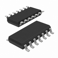
AU5790D14/N,112 NXP Semiconductors, AU5790D14/N,112 Datasheet - Page 6

AU5790D14/N,112
Manufacturer Part Number
AU5790D14/N,112
Description
IC CAN TRANSCEIVER 14-SOIC
Manufacturer
NXP Semiconductors
Series
AUr
Type
Transceiverr
Datasheet
1.AU5790D112.pdf
(20 pages)
Specifications of AU5790D14/N,112
Number Of Drivers/receivers
1/1
Protocol
CAN
Voltage - Supply
5.3 V ~ 27 V
Mounting Type
Surface Mount
Package / Case
14-SOIC (3.9mm Width), 14-SOL
Lead Free Status / RoHS Status
Lead free / RoHS Compliant
Other names
568-3054-5
935277456112
AU5790D14/N
935277456112
AU5790D14/N
1. Test pulses are coupled to CANH through a series capacitance of 1 nF.
2. Rise time for test pulse 1: t
Philips Semiconductors
ABSOLUTE MAXIMUM RATINGS
According to the IEC 134 Absolute Maximum System: operation is not guaranteed under these conditions; all voltages are referenced to
pin 8 (GND); positive currents flow into the IC, unless otherwise specified.
NOTES:
2001 May 18
V BAT
V BATld
V BATtr2
V BATtr3
V CANH_1
V
V CANHtr1
V CANHtr2
V CANHtr3
V
V
V I
ESD BAHB
ESD
ESD
ESD
R
T amb
T stg
T vj
RTH1
RTH0
Single wire CAN transceiver
SYMBOL
Tmin
CANH_0
CHHB
RTHB
LGHB
Supply voltage
Short-term supply voltage
Transient supply voltage
Transient supply voltage
CANH voltage
CANH voltage
Transient bus voltage
Transient bus voltage
Transient bus voltage
Pin RTH voltage
Pin RTH voltage
DC voltage on pins TxD, EN, RxD, NSTB
ESD capability of pin BAT
ESD capability of pin CANH
ESD capability of pin RTH
ESD capability of pins TxD, NSTB, EN, RxD, and
RTH
Bus load resistance R
RTH
Operating ambient temperature
Storage temperature
Junction temperature
r
< 1 s; pulse 2: t
PARAMETER
T
being connected to pin
r
< 100 ns; pulses 3a/3b: t
Steady state
Load dump; ISO7637/1 test pulse 5
(SAE J1113, test pulse 5), T < 1s
ISO 7637/1 test pulse 2 (SAE J1113,
test pulse 2), with series diode and
bypass cap of 100 nF between BAT and
GND pins, Note 2.
ISO 7637/1 pulses 3a and 3b
(SAE J1113 test pulse 3a and 3b),
Note 2.
V
V
ISO 7637/1 test pulse 1, Notes 1 and 2
ISO 7637/1 test pulse 2, Notes 1 and 2
ISO 7637/1 test pulses 3a, 3b,
Notes 1 and 2
V
via a 2 k series resistor
V
via a 2 k series resistor
Direct contact discharge,
R=1.5 k , C=100 pF
Direct contact discharge,
R=1.5 k , C=100 pF
Direct contact discharge,
R=1.5 k + 3 k , C=100 pF
Direct contact discharge,
R=1.5 k , C=100 pF
BAT
BAT
BAT
BAT
6
r
> 2 V
< 2 V
> 2 V, voltage applied to pin RTH
< 2 V, voltage applied to pin RTH
< 5 ns.
CONDITIONS
–150
–100
–150
MIN.
–0.3
–0.3
–10
–16
–10
–16
–40
–40
–40
–8
–8
–8
–2
2
MAX.
+100
+100
+100
+125
+150
+150
AU5790
+100
+27
+40
+18
+18
+18
+18
+7
+8
+8
+8
+2
Product data
UNIT
k
kV
kV
kV
kV
V
V
V
V
V
V
V
V
V
V
V
V
C
C
C


