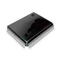
STM32L152VBT6 STMicroelectronics, STM32L152VBT6 Datasheet - Page 73

STM32L152VBT6
Manufacturer Part Number
STM32L152VBT6
Description
16/32-BITS MICROS
Manufacturer
STMicroelectronics
Series
STM32r
Datasheet
1.STM32L152-EVAL.pdf
(107 pages)
Specifications of STM32L152VBT6
Processor Series
STM32L152
Core
ARM Cortex M3
Data Bus Width
32 bit
Program Memory Type
Flash
Program Memory Size
128 KB
Data Ram Size
16 KB
Interface Type
I2C, SPI, USART
Maximum Clock Frequency
32 MHz
Number Of Programmable I/os
80
Number Of Timers
6
Operating Supply Voltage
1.8 V to 3.6 V
Maximum Operating Temperature
+ 85 C
Mounting Style
SMD/SMT
Package / Case
LQFP-100
Core Processor
ARM® Cortex-M3™
Core Size
32-Bit
Speed
32MHz
Connectivity
I²C, IrDA, LIN, SPI, UART/USART, USB
Peripherals
Brown-out Detect/Reset, DMA, I²S, LCD, POR, PWM, WDT
Number Of I /o
83
Eeprom Size
4K x 8
Ram Size
16K x 8
Voltage - Supply (vcc/vdd)
1.65 V ~ 3.6 V
Data Converters
A/D 24x12b; D/A 2x12b
Oscillator Type
Internal
Operating Temperature
-40°C ~ 85°C
Lead Free Status / Rohs Status
Details
Available stocks
Company
Part Number
Manufacturer
Quantity
Price
Company:
Part Number:
STM32L152VBT6
Manufacturer:
STMicroelectronics
Quantity:
10 000
Part Number:
STM32L152VBT6
Manufacturer:
ST
Quantity:
20 000
Company:
Part Number:
STM32L152VBT6TR
Manufacturer:
STMicroelectronics
Quantity:
10 000
STM32L151xx, STM32L152xx
Table 37.
1. FT = 5V tolerant. To sustain a voltage higher than V
2. 0.7V
3. FT = Five-volt tolerant.
4. Hysteresis voltage between Schmitt trigger switching levels. Based on characterization, not tested in production.
5. With a minimum of 200 mV. Based on characterization, not tested in production.
6. The max. value may be exceeded if negative current is injected on adjacent pins.
7. Pull-up and pull-down resistors are designed with a true resistance in series with a switchable PMOS/NMOS. This
Symbol
R
R
C
I
MOS/NMOS contribution to the series resistance is minimum (~10% order)
lkg
PU
PD
IO
DD
for 5V-tolerant receiver
Input leakage current
Weak pull-up equivalent resistor
Weak pull-down equivalent resistor
I/O pin capacitance
I/O static characteristics (continued)
Output driving current
The GPIOs (general purpose input/outputs) can sink or source up to ±8 mA, and sink or
source up to ±20 mA with the non-standard V
in the user application, the number of I/O pins which can drive current must be limited to
respect the absolute maximum rating specified in
●
●
Output voltage levels
Unless otherwise specified, the parameters given in
performed under ambient temperature and V
Table
The sum of the currents sourced by all the I/Os on V
consumption of the MCU sourced on V
I
The sum of the currents sunk by all the I/Os on V
consumption of the MCU sunk on V
I
VDD
VSS
9. All I/Os are CMOS and TTL compliant.
Parameter
(see
(see
Table
Table
(6)
7).
7).
(7)
(7)
Doc ID 17659 Rev 4
DD
switches and LCD
I/Os with analog
I/Os with analog
V
V
V
V
V
+0.5 the internal pull-up/pull-down resistors must be disabled.
I/Os with USB
I/Os with LCD
Standard I/Os
SS
SS
SS
SS
SS
Conditions
V
V
switches
IN
IN
V
V
V
V
V
SS
IN
IN
IN
IN
IN
V
V
SS
DD
DD,
cannot exceed the absolute maximum rating
V
V
V
V
V
DD
OL
DD
DD
DD
DD
DD
cannot exceed the absolute maximum rating
/V
supply voltage conditions summarized in
Section
OH
.
Table 38
specifications given in
SS
Min
30
30
plus the maximum Run
DD,
6.2:
plus the maximum Run
are derived from tests
Electrical characteristics
Typ
45
45
5
Table
TBD
Max
50
50
50
50
60
60
38.
73/107
Unit
nA
k
k
pF


