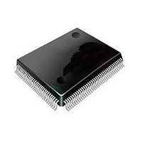
STM32L152VBT6 STMicroelectronics, STM32L152VBT6 Datasheet - Page 106

STM32L152VBT6
Manufacturer Part Number
STM32L152VBT6
Description
16/32-BITS MICROS
Manufacturer
STMicroelectronics
Series
STM32r
Datasheet
1.STM32L152-EVAL.pdf
(107 pages)
Specifications of STM32L152VBT6
Processor Series
STM32L152
Core
ARM Cortex M3
Data Bus Width
32 bit
Program Memory Type
Flash
Program Memory Size
128 KB
Data Ram Size
16 KB
Interface Type
I2C, SPI, USART
Maximum Clock Frequency
32 MHz
Number Of Programmable I/os
80
Number Of Timers
6
Operating Supply Voltage
1.8 V to 3.6 V
Maximum Operating Temperature
+ 85 C
Mounting Style
SMD/SMT
Package / Case
LQFP-100
Core Processor
ARM® Cortex-M3™
Core Size
32-Bit
Speed
32MHz
Connectivity
I²C, IrDA, LIN, SPI, UART/USART, USB
Peripherals
Brown-out Detect/Reset, DMA, I²S, LCD, POR, PWM, WDT
Number Of I /o
83
Eeprom Size
4K x 8
Ram Size
16K x 8
Voltage - Supply (vcc/vdd)
1.65 V ~ 3.6 V
Data Converters
A/D 24x12b; D/A 2x12b
Oscillator Type
Internal
Operating Temperature
-40°C ~ 85°C
Lead Free Status / Rohs Status
Details
Available stocks
Company
Part Number
Manufacturer
Quantity
Price
Company:
Part Number:
STM32L152VBT6
Manufacturer:
STMicroelectronics
Quantity:
10 000
Part Number:
STM32L152VBT6
Manufacturer:
ST
Quantity:
20 000
Company:
Part Number:
STM32L152VBT6TR
Manufacturer:
STMicroelectronics
Quantity:
10 000
Revision history
106/107
Table 65.
25-Feb-2011
Date
Document revision history (continued)
Revision
cont’d
4
Updated
Standby mode
Table 20: Typical and maximum timings in Low power
condition for Wakeup from Stop mode, regulator in Run mode; updated
max values for Wakeup from Stop mode, regulator in low power mode;
updated max values for t
Table 21: Peripheral current
Low power sleep and run; updated Flash values; renamed ADC1 to
ADC; updated I
and I
ADC.
Table 22: High-speed external user clock
value for t
t
values.
Table 23: Low-speed external user clock
value for I
Table 24: HSE 1-24 MHz oscillator
and updated max value; updated max values for I
Table 25: LSE oscillator characteristics (fLSE = 32.768
max value for I
Table 26: HSI oscillator
values for ACC
Table 28: MSI oscillator
max values for D
Table 31: Flash memory
Table 39: I/O AC
and 11; updated min value; updated footnotes.
Table 50: ADC
conditions for ENOB, SINAD, SNR, and THD.
Table 52: DAC
8.
Updated leakage value in
the
Added
supply pin during ADC
Added
Figure 28: Power supply and reference decoupling (VREF+ not
connected to
capacitors.
Figure 29: Power supply and reference decoupling (VREF+ connected
to
r(HSE)
VDDA): replaced 10 nF capacitor with 100 nF capacitor.
ADC.
Doc ID 17659 Rev 4
DD (IWDG)
/t
Figure 27: Maximum dynamic current consumption on VREF+
Table 51: RAIN max for fADC = 16 MHz(1)
f(HSE)
Table 19: Typical and maximum current consumptions in
w(HSE)
L
.
OSC_IN rise or fall time; updated I
VDDA): replaced all 10 nF capacitors with 100 nF
; updated footnote 1 and 3; added foot note 2 concerning
LSE
HSI
characteristics: updated footnote 7 and added footnote
(I
accuracy: updated typ values and some of the test
DD (LCD)
/t
DD
VOLT(MSI)
characteristics: updated some max values for 01, 10,
w(HSE)
.
.
(WU from Standby) instead of (I
conversion.
value; updated units; added values for I
characteristics: updated some min and max
characteristics: updated parameter, typ, and
OSC_IN high or low time; added max value for
WUSTDBY
characteristics: updated typ values for t
.
Figure 26: Typical connection diagram using
consumption: updated values for column
Changes
.
characteristics: renamed i
STM32L151xx, STM32L152xx
characteristics: updated max
characteristics: added min
L
DD(HSE)
for typ and max
DD
modes: updated
(WU from Stop).
kHz): updated
.
2
as I
DD (RTC)
prog
HSE
.


