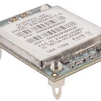
WLNG-SP-DP551 Quatech, WLNG-SP-DP551 Datasheet - Page 27

WLNG-SP-DP551
Manufacturer Part Number
WLNG-SP-DP551
Description
WiFi / 802.11 Modules & Development Tools WIRELESS DEV SERVER 802.11 B/G SPI
Manufacturer
Quatech
Series
Airborne™r
Specifications of WLNG-SP-DP551
Wireless Frequency
2.48 GHz
Interface Type
SPI
Modulation
DBPSK, DQPSK, CCK, BPSK, QPSK, 16QAM, 64QAM
Security
64/128 bit WEP, WPA, AES, EAP
Antenna
U.FL
Operating Temperature Range
- 40 C to + 85 C
Mfg Application Notes
Transition to DP550 Devices AppNote
Frequency
2.4GHz ~ 2.4835GHz
Data Rate - Maximum
54Mbps
Modulation Or Protocol
802.11 b/g
Applications
WLAN
Power - Output
-
Sensitivity
-98dBm
Voltage - Supply
3.3VDC
Current - Receiving
310mA
Current - Transmitting
240mA
Data Interface
Connector, 36 Pin Header
Memory Size
-
Antenna Connector
U.FL x 2
Operating Temperature
-40°C ~ 85°C
Package / Case
Module
Lead Free Status / Rohs Status
Details
For Use With/related Products
ARM 9, AR6002
100-8090-100
8.3
8.4
used. There are many options for the antenna connector type, however if you
wish to utilize the FCC/IOC modular approval the connector choice must comply
with FCC regulations, these state a non-standard connector is required e.g.
TNC/SMA are not allowed, RP-TNC/RP-SMA are allowed.
Host Chassis Mounted Antenna
Host Chassis mounted antennas require no work on the host PCB. They utilize
an antenna type called ‘flying lead’. There are two types of flying leads; one
which provides a bulkhead mounted antenna connector and one which provides
a bulk head mounted antenna. The type you choose will be determined by the
application.
A flying lead system connects a U.FL coaxial lead to the radio’s U.FL connector,
the other end of the coax is attached to either a bulkhead mounted antenna
connector or directly to an antenna that has an integrated bulkhead mount.
In either of the two cases, the use of this approach significantly reduces the
antenna system development effort and provides for greater flexibility in the
available antenna types and placement in the host system chassis.
When using the flying lead antenna (integrated bulk head mounting), there are no
connector choice restrictions for use with the FCC/IOC modular certification.
However if the flying lead connector is used, the same restrictions as identified
for the Host Mounted Antenna apply.
There are many suppliers of flying lead antenna and connectors; Quatech’s
Airborne Antenna product line offers a range of antenna solutions.
Embedded Antenna
Use of Embedded antenna can be the most interesting approach for M2M,
industrial and medical applications. Their small form factor and absence of any
external mounting provides a very compelling argument for their use. There is a
downside to this antenna type and it comes with performance. Antenna
performance for all of the embedded options will, in most cases, be less that that
achievable with external antenna. This does not make them unusable; it will
impact choice of antenna type and requires more focus on placement.
The three main embedded antenna types are PCB embedded, chip (PCB
mounted) and flying lead; each has its advantages and disadvantages (See
Table 17).
Antenna Type
PCB Embedded
Chip
Flying Lead
Table 17 - Embedded Antenna Options
4/14/2011
Lowest
Cost
Low
Low
Largest
Small
Small
Size
Features
Availability
Standard
Standard
Custom
Performance
Quatech, Inc.
Poor
Poor
Fair
27


