WLNG-SP-DP551 Quatech, WLNG-SP-DP551 Datasheet
WLNG-SP-DP551
Specifications of WLNG-SP-DP551


Related parts for WLNG-SP-DP551


WLNG-SP-DP551 Summary of contents
Page 1
Product Specification 802.11b/g Advanced Enterprise Device Server Revision: v1.0 April 2011 File name: dp550 platform product specification.doc Document Number: 100-8090-100 ...
Page 2
... Quatech, Inc. 2 <Page Intentionally Left Blank> 4/14/2011 100-8090-100 ...
Page 3
... Inc. has made commercially reasonable efforts to ensure that the information contained in this document is accurate and reliable. However, the information is subject to change without notice. No responsibility is assumed by QUATECH for the use of the information or for infringements of patents or other rights of third parties. This document is ® ...
Page 4
... Quatech, Inc. 4 <Page Intentionally Left Blank> 4/14/2011 100-8090-100 ...
Page 5
... Regulatory Certification and Agency Approvals ................................................................................................. 34 12.1 FCC Statement ............................................................................................................................................. 34 12.2 FCC RF Exposure Statement ....................................................................................................................... 35 12.3 Information for Canadian Users (IC Notice) .................................................................................................. 35 12.4 FCC/IC Modular Approval ............................................................................................................................. 36 12.5 End Product Labeling ................................................................................................................................... 37 12.6 Regulatory Test Mode Support ..................................................................................................................... 37 13.0 Physical & Environmental Approvals ................................................................................................................. 39 14.0 Change Log ...................................................................................................................................................... 40 100-8090-100 Contents 4/14/2011 Quatech, Inc. 5 ...
Page 6
... Quatech, Inc. Figures Figure 1 - WLNG-SE/SP/AN/ET-DP550 Block Diagram ..................................................................................................... 9 Figure 2 - SPI Read/Write Timing .................................................................................................................................... 21 Figure 3 - SPI Clock and Select Timing ............................................................................................................................ 21 Figure 4 - Power on RESET Timing ................................................................................................................................. 31 Figure 5 - RESET Timing ................................................................................................................................................. 31 Figure 6 – DP550 Mechanical Outline .............................................................................................................................. 32 Figure 7 - Recommended PCB Footprint ......................................................................................................................... 33 Figure 8 - Full FCC/IC Label ............................................................................................................................................ 37 Figure 9 - Minimum FCC/IC Label .................................................................................................................................... 37 Tables Table 1 - Model Numbers ...
Page 7
... The following section outlines the conventions used within the document, where convention is deviated from the deviation takes precedence and should be followed. If you have any question related to the conventions used or clarification of indicated deviation please contact Quatech Sales or Wireless Support. 1.1 Terminology Airborne Enterprise Device Server and AirborneDirect Enterprise Device ...
Page 8
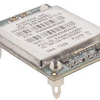
... Quatech, Inc. 2.0 Product Description The WLNG-AN-DP550 family is the latest generation of 802.11 wireless device servers and adapters from Quatech. The radio features the following: 802.11b/g WiFi Radio with 32bit ARM9 CPU (128MB SDRAM, 64MB Flash) Atheros AR6002 802.11b/g radio chipset. ...
Page 9
... Block Diagram The following outlines the block diagram of the radio: Figure 1 - WLNG-SE/SP/AN/ET-DP550 Block Diagram 100-8090-100 4/14/2011 Quatech, Inc. 9 ...
Page 10
... Description WLNG-AN-DP551 802.11b/g, UART device server 802.11b/g, 10/100 Ethernet device WLNG-ET-DP551 adapter 802.11b/g, UART device server WLNG-SE-DP551 with RS232/422/485 driver control WLNG-SP-DP551 802.11b/g, SPI device server WLNG-EK-DP551 802.11b/g Enterprise Class Serial Device Server Module Evaluation Kit 10 Table 1 - Model Numbers WiFi Interface 2 ...
Page 11
... No Connect SPI No Connect Ethernet Ethernet RX- All Digital Ground All Digital Ground UART Ready-to-Send UART2 Serial Line Driver Tx enable SPI Ready-to-Send UART2 Ethernet Ready-to-Send UART2 All GPIO UART Ready-to-Send UART1 Serial Ready-to-Send SPI SPI Clock Input Ethernet Ready-to-Send UART1 4/14/2011 Quatech, Inc. 11 ...
Page 12
... Quatech, Inc. Pin Name F4 CTS2 RXEN 19 CTS2 CTS2 G1 20 TCK TXD2 TXD2 21 TXD2 TXD2 G7 G0 SER_MODE 22 SPI_INT G0 LED_CON 23 F6 RXD1 RXD1 24 MOSI RXD1 F7 LED_POST 25 F0 LED_WLN_CFG 26 F3 LED_RF_LINK 27 F2 TXD1 TXD1 28 MISO TXD1 TX TX+ 31 NTRST 32 TMS 33 VDD 34 VDD 35 LED_RF_ACT 36 GND 12 Device ...
Page 13
... The interface also supports both half and full duplex for 10Mbps and 100Mbps. The interface uses a Broadcom BCM5241A Ethernet PHY, please refer to the manufacturers datasheet for interface details and appropriate design guidelines. 100-8090-100 Table 3 - UART Pin Definition UART Serial UART1 UART2 UART1 Pin Pin Pin 4/14/2011 Quatech, Inc. All UART2 Debug Pin ...
Page 14
... It is recommended that a connection to this port be supported via test points or a two pin header. The default settings for the debug port are 115200 Flow Control. CAUTION: Do not use the debug port without contacting Quatech Technical Support first. Potential damage to the module may occur. 5.5 General Purpose Input/Output (GPIO) A number of the interface pins support multiple functional definitions ...
Page 15
... Hirose: DF12B-36DP-0.5V(XX) (0.50mm (.020") Pitch Plug, Surface Mount, Dual Row, Vertical, 4.00mm Stack Height, 36 Circuits) RF connector for 802.11b/g antenna (Default). Hirose U.FL RF connector for 802.11b/g antenna. Hirose U.FL. Bottom Top View CN3 CN2 Component RF Shield Area CN1 4/14/2011 Quatech, Inc. View 15 ...
Page 16
... Quatech, Inc. 6.0 Electrical & RF Specification Parameter Supply Voltage Power Dissipation Operating Temperature Range Storage Temperature Note: 1. Values are absolute ratings, exceeding these values may cause permanent damage to the device. Table 5 – Operating Conditions & DC Specification Symbol Parameter V Supply Voltage DD V Input Low Level Voltage ...
Page 17
... CPU Idle, wake on Network traffic I Sleep Mode – UART/Serial SB3U Radio Off (disassociated) CPU Idle, wake on UART traffic I Sleep Mode – Ethernet SB3E Radio Off (disassociated) CPU Idle 100-8090-100 Min Typ 150 130 160 110 110 4/14/2011 Quatech, Inc. Max Units 150 mA 17 ...
Page 18
... Quatech, Inc. Table Characteristics – 802.11b/g Symbol Parameter Transmit Power P OUTB Output 802.11b Transmit Power P OUTG Output 802.11g Receive P Sensitivity RSENB 802.11b Receive P Sensitivity RSENG 802.11g Frequency F RANGEBG Range Table 7 - Supported Data Rates by Band Band 802.11b 802.11g Band Region US/Canada 802.11b ...
Page 19
... Table 9 - Radio Typical Performance Range Typical Outdoor Distance Typical Outdoor Distance (2dBi antenna gain on each end for (Unity gain antenna) 240m 135m 135m 12m 4/14/2011 Quatech, Inc. B/G mode) 380m 215m 215m 19m 19 ...
Page 20
... Quatech, Inc. 7.0 SPI Interface The following section details the SPI interface specification for both hardware timing and SPI protocol. The device is a SPI slave and requires a compatible SPI master for operation. 7.1 Pin-out When the SPI interface is enabled, through the CLI or web interface, the following pins are assigned for communication ...
Page 21
... Clock Low to Data In Valid Set-up time Clock Low to Data Valid Hold time Clock Falling Edge to SPI Select High SPI Select High to SPI Select Low Figure 2 - SPI Read/Write Timing Figure 3 - SPI Clock and Select Timing 4/14/2011 Quatech, Inc. Min Typ Max Units 8.00 MHz ...
Page 22
... Quatech, Inc. 7.3 SPI Protocol A SPI message is composed byte header followed more bytes of data. The header data is full-duplex. That is, the TX message header is sent to the Airborne Device Server module by the host at the same time the RX message header is sent to the host from the Airborne Device Server. ...
Page 23
... TX interrupt command on a common UART. The result of this command is that the TX interrupt is cleared even though the host is not writing more data to the module. PARM1 and PARM2 are unused for this command and should be set to zero. 4/14/2011 Quatech, Inc. Clocking Edge 23 ...
Page 24
... Quatech, Inc. Command (Hex) 0x10 0x20 24 Name Description INTENA The INTENA command will configure the specific interrupts to be enabled from the module. For this command, the PARM1 field will define the interrupts to be enabled. The definition of the PARM1 field for this command is a bit-mask ...
Page 25
... RX Data Available field. If additional clock cycles are sent to the module beyond this number, meaningless data will be returned. PARM1 is unused for this command and should be set to zero. 4/14/2011 Quatech, Inc. 25 ...
Page 26
... U.FL connector to the antenna mount. There are several sources for the U.FL to U.FL coaxial cable these include Hirose, Sunridge and IPEX. Please contact Quatech for further part numbers and supply assistance. This approach can simplify assembly but does require that the host system configuration can accommodate an antenna location that is determined by the host PCB ...
Page 27
... FCC/IOC modular certification. However if the flying lead connector is used, the same restrictions as identified for the Host Mounted Antenna apply. There are many suppliers of flying lead antenna and connectors; Quatech’s Airborne Antenna product line offers a range of antenna solutions. 8.4 ...
Page 28
... Minimize the distance between the radio and the location of the antenna. The coaxial cable between the two impacts the Transmit Power and Receive Sensitivity negatively. Quatech recommends using 1.32-1.37mm outer diameter U.FL coaxial cables. Minimize the locations where metal surfaces come into contact or are close to the location of the antenna. ...
Page 29
... The antenna gain contributes to the Equivalent Isotropically Radiated Power (EIRP) of the system. This is part of an overall measurement of the link quality called link margin. 100-8090-100 4/14/2011 Quatech, Inc. 29 ...
Page 30
... Link Margin (dB) = EIRP – FPL + (RxS + RxA – RxC) Where: This is a complex subject and requires more information than is presented here, Quatech recommends at reviewing the subject and evaluating any system at a basic level then possible, with a combination of the above items and an understanding of the application demands, to achieve a link quality optimized for the application and host design ...
Page 31
... RESET Function For correct operation of the on-board Power-on RESET (POR) and internal RESET controllers, the RESET pin on the WLNG-XX-DP550 family must obey the following timing and signal conditions. Symbol Parameter t Valid V PURST DD t RESET Valid to RESET Low RLRV t Valid V RPWI ...
Page 32
... Quatech, Inc. 10.0 Mechanical Outline 29.60mm 32.00mm 40.60mm 16.00mm CN1 2 1 Hirose DF12-36DS-0.5V 10.50mm 21.00mm BOTTOM VIEW Dimensions: mm Tolerance: ± 0.15 (unless noted) Module Connector: Board Connector: RF Connector: The mounting hardware for the DP550 device utilizes a friction fit for retention of the thru-hole pins to the host board. ...
Page 33
... PCB and the DP550 stand-off hardware. Nominal Radius: Tolerance: Host Board Thickness: 0.8mm to 1.6mm 11.2 Alternate Mounting Hardware Quatech does support alternate mounting hardware for the DP550 platform. Please contact your Quatech sales representative for further details. 100-8090-100 29.60mm MAX Ø5.00mm (X4) 16.00mm ...
Page 34
... Regulatory Certification and Agency Approvals IMPORTANT! required that the following section be read and understood before use of the Quatech Airborne™ device is permitted. Use of approved antenna is required for compliance to FCC and IC regulations. The unit complies with the following agency approvals: ...
Page 35
... Industry Canada. The required antenna impedance is 50Ω. Only approved antenna may be used with this equipment. Quatech maintains a full list of approved antenna, please contact your Quatech representative for the up to date list. To reduce potential radio interference to other users, the antenna type and its gain should be so chosen that the Equivalent Isotropically Radiated Power (EIRP) is not more than required for successful communication ...
Page 36
... FCC/IC Modular Approval This document describes the Airborne WLN FCC modular approval and the guidelines for use as outlined in FCC Public Notice (DA 00-1407). The WLNG-XX-DP550 is covered by the following modular grants: Country North America (US) Canada ...
Page 37
... Industry of Canada Grant numbers as shown in Table 20. The following label or similar must be placed on the outside of the product, utilizing the Airborne™ device, whenever physically possible: Contains Transmitter Module, FCC ID: F4AWLNG551 Contains Canadian Certification Number, IC: 3913A-WLNG551 The radio component is an integral part of the equipment and cannot be removed. ...
Page 38
... Quatech, Inc. contact Quatech Technical Support for details on enabling and using these modes. 38 4/14/2011 100-8090-100 ...
Page 39
... Operational) Humidity Altitude Vibration Shock Product Drop Packaging Drop Accelerated Life Test Test reports are available from Quatech Technical Support, please contact directly for the latest documentation. 100-8090-100 Table 21 - Mechanical Approvals Reference Table 1B, Type 2b 0-95%RH @ 38°C condensing Sect 4.2.3 Fig 4a – 8 hours active humidity cycle Operational: 0-12,000ft (62 KPa absolute pressure) Sect 4 ...
Page 40
... Quatech, Inc. 14.0 Change Log The following table indicates all changes made to this document: Version Date Section 1.0 4/14/2011 40 Change Description - Initial release 4/14/2011 Author ACR 100-8090-100 ...