WLNG-SP-DP551 Quatech, WLNG-SP-DP551 Datasheet - Page 24
WLNG-SP-DP551
Manufacturer Part Number
WLNG-SP-DP551
Description
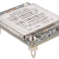
WiFi / 802.11 Modules & Development Tools WIRELESS DEV SERVER 802.11 B/G SPI
Manufacturer
Quatech
Series
Airborne™r
Specifications of WLNG-SP-DP551
Wireless Frequency
2.48 GHz
Interface Type
SPI
Modulation
DBPSK, DQPSK, CCK, BPSK, QPSK, 16QAM, 64QAM
Security
64/128 bit WEP, WPA, AES, EAP
Antenna
U.FL
Operating Temperature Range
- 40 C to + 85 C
Mfg Application Notes
Transition to DP550 Devices AppNote
Frequency
2.4GHz ~ 2.4835GHz
Data Rate - Maximum
54Mbps
Modulation Or Protocol
802.11 b/g
Applications
WLAN
Power - Output
-
Sensitivity
-98dBm
Voltage - Supply
3.3VDC
Current - Receiving
310mA
Current - Transmitting
240mA
Data Interface
Connector, 36 Pin Header
Memory Size
-
Antenna Connector
U.FL x 2
Operating Temperature
-40°C ~ 85°C
Package / Case
Module
Lead Free Status / Rohs Status
Details
For Use With/related Products
ARM 9, AR6002


Quatech, Inc.
24
Command
(Hex)
0x10
0x20
INTENA
INTDIS
Name
4/14/2011
PARM2 is unused for this command and should be set to zero.
For example, to enable TX interrupts with the interrupt pin
active high, use the SPI message 0x10 0x82 0x00 0x00. That
is, SPI command 0x10, PARM1 is 0x82, PARM2 is 0x0000.
Important: The INTENA command can only be used to enable
the specified interrupts. This command cannot be used to
disable specified interrupts by setting the corresponding
interrupt enable bits to zero in PARM1. The INTDIS command
must be used to disable the specified interrupts.
Description
The INTENA command will configure the specific interrupts to
be enabled from the module. For this command, the PARM1
field will define the interrupts to be enabled.
The definition of the PARM1 field for this command is a bit-mask
and is formatted as follows:
Bit 7
Bit 1
Bit 0
The INTDIS command will configure the specific interrupts to be
disabled from the module. For this command, the PARM1 field
will define the interrupts to be disabled.
The definition of the PARM1 field for this command is a bit-mask
and is formatted as follows:
Bit 1
Bit 0
PARM2 is unused for this command and should be set to zero.
For example, to disable TX interrupts, use the SPI message
0x20 0x02 0x00 0x00. That is, SPI command 0x20, PARM1 is
0x02, PARM2 is 0x0000.
Interrupt Sense – Determines the asserted state of
the interrupt pin. If this bit is set to a 1, the interrupt
pin will be active high; otherwise the interrupt pin will
be active low. The module will use the setting of this
bit from the most recently issued INTENA command
to determine the Interrupt Sense.
TX Interrupt – If this bit is set to a 1, the interrupt
pin will be asserted when there is space available in
the TX buffer. The interrupt will be cleared when the
module has TX data to process from the host.
Alternately, the host can clear this interrupt by using
the TXINTCLR command if the host has no more data
to send.
RX Interrupt – If this bit is set to a 1, the interrupt
pin will be asserted when there is RX data available.
The interrupt will be cleared when the host has
received all the RX data available from the module.
All other bits of PARM1 are unused for this command
and should be set to zero.
TX Interrupt – If this bit is set to a 1, The TX
interrupt function will be disabled.
RX Interrupt – If this bit is set to a 1, the RX
interrupt function will be disabled.
All other bits of PARM1 are unused for this command
and should be set to zero.
100-8090-100
Related parts for WLNG-SP-DP551
Image
Part Number
Description
Manufacturer
Datasheet
Request
R

Part Number:
Description:
MODULE 802.11B/G SPI INTERFACE
Manufacturer:
Quatech
Datasheet:

Part Number:
Description:
EVAL KIT ETHERNET-802.11B/G
Manufacturer:
Quatech
Datasheet:

Part Number:
Description:
EVAL KIT SPI TO 802.11B/G
Manufacturer:
Quatech
Datasheet:

Part Number:
Description:
KIT EVAL/DEV FOR 802.11G MODULES
Manufacturer:
Quatech
Datasheet:

Part Number:
Description:
MODULE 802.11B/G ETHERNET BRIDGE
Manufacturer:
Quatech
Datasheet:

Part Number:
Description:
MODULE 802.11B/G SERIAL BRIDGE
Manufacturer:
Quatech
Datasheet:

Part Number:
Description:
MODULE 802.11B/G UART RS-232
Manufacturer:
Quatech
Datasheet:

Part Number:
Description:
WiFi / 802.11 Modules & Development Tools Airborne Device Serv er UI to 802.11b/g
Manufacturer:
Quatech
Datasheet:
Part Number:
Description:
KIT EVAL 802.11B/G UNVRSL INTFC
Manufacturer:
Quatech
Datasheet:

Part Number:
Description:
KIT EVAL FOR 802.11G MODULES
Manufacturer:
Quatech
Datasheet:

Part Number:
Description:
MODULE 802.11B/G UART INTERFACE
Manufacturer:
Quatech
Datasheet:

Part Number:
Description:
WiFi / 802.11 Modules Airborne 802.11 b/g AP&Dvc Server Indust
Manufacturer:
B&B Electronics (Quatech)
Part Number:
Description:
WiFi / 802.11 Modules Airborne 802.11 b/g Access Point Module
Manufacturer:
B&B Electronics (Quatech)
Datasheet:
Part Number:
Description:
USB Interface IC USB Over Ethernet Server, 4 Port
Manufacturer:
B&B Electronics (Quatech)
Datasheet:
Part Number:
Description:
USB Interface IC 8Port USB-RS-232/422 /485 Serial Adapter
Manufacturer:
B&B Electronics (Quatech)