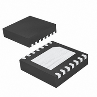
MAX13342EETD+T Maxim Integrated Products, MAX13342EETD+T Datasheet - Page 9

MAX13342EETD+T
Manufacturer Part Number
MAX13342EETD+T
Description
IC TXRX USB FS 3WIRE 14-TDFN
Manufacturer
Maxim Integrated Products
Type
Transceiverr
Datasheet
1.MAX13345EETDT.pdf
(18 pages)
Specifications of MAX13342EETD+T
Number Of Drivers/receivers
1/1
Protocol
USB 2.0
Voltage - Supply
2.3 V ~ 3.6 V
Mounting Type
Surface Mount
Package / Case
14-TDFN Exposed Pad
Lead Free Status / RoHS Status
Lead free / RoHS Compliant
The MAX13342E/MAX13345E control signals are used
to control the USB D+/D- lines. V
side interface and sets the input and output thresholds
of these signals. The control signals for the MAX13342E
and MAX13345E are DAT, SE0, and
See Table 1 for various power-supply configurations.
V
V
to +3.6V supply. V
the USB connector. An internal regulator provides 3.3V
to internal circuitry, and a regulated 3.3V output at
V
resistor. The MAX13342E and MAX13345E can be
powered by connecting both V
external regulator.
Operate the transceivers in low-power mode by assert-
ing SUS high. In low-power mode, the USB differential
receiver is turned off and V
Table 1. Power-Supply Configuration
Table 2. Disable-Mode and Sharing-Mode Connection
BUS
BUS
TRM
GND or Floating
3-Wire Interface Full-Speed USB Transceivers
, in addition to powering the internal D+ pullup
supplies power to the USB transceivers. Connect
to a +4V to +5.5V supply. Connect V
+4.0 to +5.5
+4.0 to +5.5
V
BUS
INPUTS/OUTPUTS
(V)
V
D+ and D-
BUS
DAT, SE0
SUS
BD
_______________________________________________________________________________________
V
BUS
/ V
L
Power-Supply Configuration
TRM
With/Without Internal Series Resistors
is typically connected directly to
+3.0 to +3.6 output
+3.0 to +3.6 output
BUS
Normal Operating Mode
BUS
V
High Z
TRM
consumes less than
L
and V
OE.
(V)
Low-Power Mode
powers the logic-
TRM
L
Interface
to a +2.3V
Floating or connected to GND
to a 3.3V
DISABLE MODE
High impedance
High impedance
High impedance
GND or floating
+2.3 to +3.6
+2.3 to +3.6
4V to 5.5V
V
Low
L
(V)
45µA of supply current. The single-ended D+ and D-
receivers are still active when driving SUS high.
Connect V
(or V
GND. D+ and D- are tri-stated, allowing other circuitry
to share the USB D+ and D- line. V
than 5µA of supply current. When operating the trans-
ceivers in sharing mode, the SUS input is ignored, and
the interface signals (SE0, DAT) are high impedance.
Connect V
unconnected or connect to ground. In disable mode,
D+ and D- are tri-stated, and V
V
ating the transceivers in disable mode, OE, SUS, and
inputs to the interface control signals are ignored.
(See Table 2.)
BUS
BUS
and V
and V
L
BUS
TRM
to a system power supply and leave V
CONFIGURATION
to a system power supply and leave V
Sharing mode
Disable mode
Normal mode
) consume less than 25µA. When oper-
TRM
) unconnected or connected to
Floating or connected to GND
SHARING MODE
2.3V to 3.6V input
High impedance
High impedance
High impedance
BUS
Low
L
and/or V
consumes less
Sharing Mode
Disable Mode
NOTES
Table 2
Table 2
—
TRM
BUS
(or
9
L


