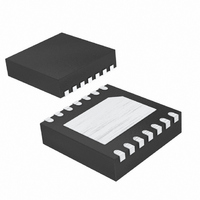
MAX13342EETD+T Maxim Integrated Products, MAX13342EETD+T Datasheet - Page 10

MAX13342EETD+T
Manufacturer Part Number
MAX13342EETD+T
Description
IC TXRX USB FS 3WIRE 14-TDFN
Manufacturer
Maxim Integrated Products
Type
Transceiverr
Datasheet
1.MAX13345EETDT.pdf
(18 pages)
Specifications of MAX13342EETD+T
Number Of Drivers/receivers
1/1
Protocol
USB 2.0
Voltage - Supply
2.3 V ~ 3.6 V
Mounting Type
Surface Mount
Package / Case
14-TDFN Exposed Pad
Lead Free Status / RoHS Status
Lead free / RoHS Compliant
The MAX13342E/MAX13345E use DAT and SE0 to
drive data or a single-ended zero onto the D+/D- lines.
When OE is low, SE0 is an input and functions as a
single-ended zero driver. When SE0 is high, both D+
and D- are driven low. When SE0 is driven low, the
D+/D- outputs are controlled by DAT.
DAT is used to send data on D+/D- when both OE and
SE0 are low. When DAT is high, D+ is driven high and
D- is driven low. When DAT is low, D+ is driven low and
D- is driven high.
In receive mode (OE = high), DAT is the output of the
differential receiver connected to D+ and D-. SE0 only
goes active high when both D+ and D- are low.
The MA13342E/MAX13345E USB detection function
indicates that V
MAX13345E push-pull bus detection output (BD) moni-
tors V
sent. BD asserts low if V
enters sharing mode.
OE controls the direction of communication when V
and V
SE0 operate as logic inputs and D+/D - are outputs.
When OE is high, DAT and SE0 operate as logic out-
puts and D+/D- are inputs.
3-Wire Interface Full-Speed USB Transceivers
With/Without Internal Series Resistors
10
______________________________________________________________________________________
BUS
BUS
, and asserts high when V
are both present. When OE is low, DAT and
BUS
is present. The MAX13342E/
BUS
3-Wire DAT/SE0 Interface
is less than +3.6V and
BUS
Control Signals
USB Detection
and V
L
are pre-
OE
L
SUS determines whether the MAX13342E/MAX13345E
operate in normal mode or in suspend mode. Drive
SUS low for normal operation. Drive SUS high to enable
suspend mode. In suspend mode, the single-ended
receivers (D+/D-) are active to detect a wake-up event.
Supply current decreases to less than 45µA in suspend
mode.
The MAX13342E/MAX13345E can transmit data on D+
and D- while in suspend mode. This function is used to
signal a remote wake-up event.
A 1.5kΩ pullup resistor on D+ is used to indicate full-
speed (12Mbps) operation. Drive ENUM high to con-
nect the internal pullup resistor from D+ to V
ENUM low to disconnect the internal pullup resistor
from D+ to V
D+ and D- are bidirectional signals and are ESD pro-
tected to ±15kV (HBM). OE controls the direction of D+
and D- when in USB normal mode (Tables 3 and 4).
An internal linear regulator generates the V
(+3.3V typ). V
Power-Supply Configuration section). V
internal USB circuitry and provides the pullup voltage
for the internal 1.5kΩ resistor. Bypass V
with a 1µF ceramic capacitor as close to the device as
possible. Do not use V
circuitry.
TRM
TRM
.
derives power from V
TRM
to provide power to external
TRM
BUS
TRM
TRM
powers the
TRM
D+ and D-
(see the
to GND
voltage
ENUM
. Drive
V
SUS
TRM


