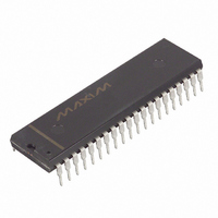
DS2181A+ Maxim Integrated Products, DS2181A+ Datasheet - Page 3

DS2181A+
Manufacturer Part Number
DS2181A+
Description
IC TXRX CEPT PRIMARY RATE 40-DIP
Manufacturer
Maxim Integrated Products
Type
Transceiverr
Datasheet
1.DS2181A.pdf
(32 pages)
Specifications of DS2181A+
Number Of Drivers/receivers
1/1
Protocol
CEPT
Voltage - Supply
4.5 V ~ 5.5 V
Mounting Type
Through Hole
Package / Case
40-DIP (0.600", 15.24mm)
Logic Type
CMOS
Supply Voltage (max)
5.5 V
Supply Voltage (min)
4.5 V
Maximum Operating Temperature
+ 70 C
Mounting Style
Through Hole
High Level Output Current
- 1 mA
Interface
DMA, CPI
Low Level Output Current
4 mA
Minimum Operating Temperature
0 C
Output Current
4 mA
Supply Current
5 mA
Supply Voltage Range
4.5V To 5.5V
Logic Case Style
LCC
No. Of Pins
44
Operating Temperature Range
0°C To +70°C
Termination Type
SMD
Transceiver Type
Network
Driver Case Style
LCC
Rohs Compliant
Yes
Filter Terminals
SMD
Interface Type
Serial
Lead Free Status / RoHS Status
Lead free / RoHS Compliant
TRANSMIT PIN DESCRIPTION (40-PIN DIP ONLY) Table 1
SYCHRONIZER STATUS PIN (44-PIN PLCC ONLY) Table 2A
PIN
PIN
10
11
12
13
25
28
1
2
3
4
5
6
7
8
9
3
6
SYMBOL
SYMBOL
TMSYNC
TCHCLK
TFSYNC
RMSA
TNEG
RCTO
TCLK
RCSA
RFSA
TSER
TIND
TPOS
TSTS
TMO
TXD
TSD
TAF
TYPE
TYPE
O
O
O
O
O
O
O
O
O
I
I
I
I
I
I
I
Transmit Multiframe Sync. Low-high transition establishes start of
CAS and/or CRC4 multiframe. Can be tied low, allowing internal
multiframe counter to run free.
Transmit Frame Sync. Low-high transition every frame period
establishes frame boundaries. Can be tied low, allowing TMSYNC to
establish frame boundaries.
Transmit Clock. 2.048 MHz primary clock.
Transmit Channel Clock. 256 kHz clock which identifies timeslot
boundaries. Useful for parallel-to-serial conversion of channel data.
Transmit Serial Data. NRZ data input, sampled on falling edges of
TCLK.
Transmit Multiframe Out. Output of multiframe counter; high
during frame 0, low otherwise.
Transmit Extra Data. Sampled on falling edge of TCLK during bit
times 5, 7, and 8 of timeslot 16 in frame 0 when CAS signaling is
enabled.
Transmit Signaling Timeslot. High during timeslot 16 of every
frame, low otherwise.
Transmit Signaling Data. CAS signaling data input; sampled on
falling edges of TCLK for insertion into outgoing timeslot 16 when
enabled.
Transmit International and National Data. Sampled on falling
edge of TCLK during bit 1 time of timeslot 0 every frame
(international) and/or during bit times 4 through 8 of timeslot 0 during
non-align frames (national) when enabled.
Transmit Alignment Frame. High during frames containing the
frame alignment signal, low otherwise.
Transmit Bipolar Data Outputs. Updated on rising edge of TCLK.
Receive Multiframe Search Active. This pin will transition high
when the synchronizer searching for the CAS multiframe alignment
word is active.
Receive Frame Search Active. This pin will transition high when the
synchronizer searching for the FAS is active.
Receive CRC4 Time Out. This pin will transition high when the
RCTO counter reaches its maximum count of 32. The pin will return
low when either the DS2181AQ reaches CRC4 multiframe
synchronization, or if CRC4 is disabled via CRC.2, or if the device is
issued a hardware reset via the
Receive CRC4 Search Active. This pin will transition high when the
synchronizer searching for the CRC4 multiframe alignment word is
active.
3 of 32
DESCRIPTION
DESCRIPTION
RST
pin.
DS2181A


