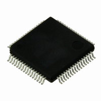
VSC8601XKN Vitesse Semiconductor Corp, VSC8601XKN Datasheet - Page 28

VSC8601XKN
Manufacturer Part Number
VSC8601XKN
Description
IC PHY 10/100/1000 64-EP-LQFP
Manufacturer
Vitesse Semiconductor Corp
Type
PHY Transceiverr
Specifications of VSC8601XKN
Number Of Drivers/receivers
1/1
Protocol
Gigabit Ethernet
Voltage - Supply
2.5V, 3.3V
Mounting Type
Surface Mount
Package / Case
64-LQFP Exposed Pad, 64-eLQFP, 64-HLQFP
Case
TQFP
Dc
06+
Lead Free Status / RoHS Status
Lead free / RoHS Compliant
Other names
907-1028
Available stocks
Company
Part Number
Manufacturer
Quantity
Price
Company:
Part Number:
VSC8601XKN
Manufacturer:
KYOCERA/AVX
Quantity:
20 000
Company:
Part Number:
VSC8601XKN
Manufacturer:
VITESSE
Quantity:
1 235
Company:
Part Number:
VSC8601XKN
Manufacturer:
Vitesse Semiconductor Corporation
Quantity:
10 000
Part Number:
VSC8601XKN
Manufacturer:
VITESSE
Quantity:
20 000
3.12
3.12.1
3.12.2
Table 3.
Revision 4.1
September 2009
Mode
0
1
Function Name
Link/activity
Link1000/activity
LED Interface
The VSC8601 device drives up to three LEDs directly. All LED outputs are active-low
and are driven using 3.3 V from the VDD33 power supply. When active, the pins are
mainly used to sink current of the cathode side of an LED, but the pins can also supply
source power to the anode portion of LEDs when they are not in the active state. This
allows for two LED pins to be used to drive a multi-status, bi-colored LED.
Simple or Enhanced LED Method
The VSC8601 provides two methods for controlling its LEDs: simple or enhanced. The
simple LED method is backward-compatible to the LED control found in prior Vitesse
Ethernet PHY devices. The simple LED method eases software backward compatibility
for customers switching to the VSC8601. The simple LED method is controlled by MII
Register 27 and is enabled by default.
For added flexibility, the VSC8601 LED can be controlled using the enhanced LED
method. The enhanced LED method is enabled by setting MII Register 17E.4 = 1. When
enabled, then the LEDs are controlled by MII Registers 16E and 17E. In this method,
the MII Register 27 settings are ignored.
Simple LED Method
simple LED method. This LED method is enabled on power-up and is controlled by MII
Register 27. In this method, MII Register 27 controls the LEDs. For more information,
see
Enhanced LED Method
enhanced LED method. In this method, MII Register 16E and 17E control the LEDs. For
more information, see
Behavior,”
LED Modes
If you are using the enhanced LED method, there are several LED modes available.
They are found in MII Register 16E. Each LED pin can be configured to display different
status information. Set the LED mode either by using register 16E or with the CMODE
pin setting. The following table summarizes the LED functions.
Note The modes listed in the following table are equivalent to the setting used in
register 16E to configure each LED pin. For the LED states listed, 1 = pin held high
(de-asserted), 0 = pin held low (asserted), and blink/pulse-stretch is dependent on the
LED behavior setting in register 17E.
LED Mode and Function Summary
“LED Control,”
page 57.
LED State and Description
1 = No link in any speed on any media interface.
0 = Valid link at any speed on any media interface.
Blink or pulse-stretch = Valid link at any speed on any media interface and
with activity present.
1 = No link in 1000BASE-T.
0 = Valid 1000BASE-T link.
Blink or pulse-stretch = Valid 1000BASE-T link with activity present.
page 52.
“Enhanced LED Method Select,”
When MII Register 17E.4 = 0, the LEDs are controlled by the
When MII Register 17E.4 = 1, the LEDs are controlled by the
page 56 and
Functional Descriptions
VSC8601 Datasheet
“Enhanced LED
Page 28


