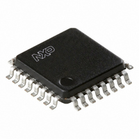
TDA8020HL/C1,118 NXP Semiconductors, TDA8020HL/C1,118 Datasheet - Page 11

TDA8020HL/C1,118
Manufacturer Part Number
TDA8020HL/C1,118
Description
IC SMART CARD INTERFACE 32LQFP
Manufacturer
NXP Semiconductors
Type
Interfacer
Datasheet
1.TDA8020HLC2118.pdf
(28 pages)
Specifications of TDA8020HL/C1,118
Voltage - Supply
2.7 V ~ 6.5 V
Mounting Type
Surface Mount
Package / Case
32-LQFP
Lead Free Status / RoHS Status
Lead free / RoHS Compliant
Number Of Drivers/receivers
-
Protocol
-
Other names
568-3523-2
935267381118
TDA8020HLBD-T
935267381118
TDA8020HLBD-T
Available stocks
Company
Part Number
Manufacturer
Quantity
Price
Company:
Part Number:
TDA8020HL/C1,118
Manufacturer:
NXP Semiconductors
Quantity:
10 000
Philips Semiconductors
R
The read status sequence is as follows:
1. START condition
2. Byte 1: ADDRESS plus read command
3. ACK: acknowledge
4. Byte 2: STATUS byte; see Table 4
5. ACK: acknowledge
6. STOP condition.
Table 4 STATUS byte bits (all bits cleared after power-on)
When one of the bits PRESL, MUTE, EARLY and PROT is set, then IRQ goes LOW until the status byte has been read.
After power-on, bit SUPL is set until the status byte has been read, and IRQ is LOW until the supervisor becomes
inactive.
Sequencers and clock counter
Two sequencers are used to ensure activation and
deactivation sequences according to ISO 7816 and
EMV 2000, even in the event of an emergency (card
removal during transaction, supply drop-out and hardware
problem).
The sequencers are clocked by the internal oscillator.
The activation of a card is initiated by setting the card
select bit and the start bit within the control register. This is
only possible if the card is present and if the voltage
supervisor is not active.
During activation the DC-to-DC converter is initiated
(except if another card is already powered up or if
V
selected voltage (3 or 5 V), the I/O lines are then enabled
and the clock is started with RST LOW.
2003 Nov 06
BIT
DD
EAD STATUS SEQUENCE
0
1
2
3
4
5
6
7
Dual IC card interface
= 5 V and V
PRES
PRESL
I/O
SUPL
PROT
MUTE
EARLY
ACTIVE
NAME
CC
= 3 V). V
set when the card is present; reset when the card is not present
set when the card has been inserted or extracted; reset when the status has been read
set when I/O is HIGH; reset when I/O is LOW
set when the supervisor has signalled a fault; reset when the status has been read
set when an overload or an overheating has occurred during a session; reset when the status
has been read
set during ATR when the selected card has not answered during the ISO 7816 time slots; reset
when the status has been read
set during ATR when the selected card has answered too early; reset when the status has been
read
set if the card is active; reset if the card is inactive
CC
then goes high to the
11
D
1. If a start bit is detected on the I/O during the first
2. If a start bit is detected between 200 and 352 CLK
3. If the card starts responding within 41950 CLK pulses,
4. If the card has not responded within 41950 CLK
5. If a start bit is detected within 352 CLK pulses, bit
6. If the card does not respond within the next 41950
7. If the card responds within the correct window period,
DESCRIPTION
EVICE TYPE
200 CLK pulses, it is ignored and the count continues.
pulses, bit EARLY is set in the status register.
RST remains LOW.
pulses, then RST goes HIGH.
EARLY is set in the status register.
CLK pulses, bit MUTE is set within the status register.
This initiates a warm reset command.
the CLK count is stopped and the system controller
may send commands to the card.
TDA8020HL/C1:
TDA8020HL
Product specification


