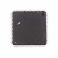
DP83934CVUL-33 National Semiconductor, DP83934CVUL-33 Datasheet - Page 20

DP83934CVUL-33
Manufacturer Part Number
DP83934CVUL-33
Description
IC CTRLR ORIENT NETWORK 160PQFP
Manufacturer
National Semiconductor
Datasheet
1.DP83934AVQB.pdf
(104 pages)
Specifications of DP83934CVUL-33
Controller Type
Network Interface Controller (NIC)
Interface
Twisted Pair
Voltage - Supply
4.75 V ~ 5.25 V
Current - Supply
140mA
Operating Temperature
0°C ~ 70°C
Mounting Type
Surface Mount
Package / Case
160-MQFP, 160-PQFP
Lead Free Status / RoHS Status
Contains lead / RoHS non-compliant
Other names
*DP83934CVUL-33
Available stocks
Company
Part Number
Manufacturer
Quantity
Price
Company:
Part Number:
DP83934CVUL-33
Manufacturer:
Texas Instruments
Quantity:
10 000
3 0 Functional Description
3 6 STATUS AND CONFIGURATION REGISTERS
The SONIC-T contains a set of status control registers for
conveying status and control information to from the host
system The SONIC-T uses these registers for loading com-
mands generated from the system indicating transmit and
receive status buffering data to from memory and provid-
ing interrupt control Each register is 16 bits in length See
Section 6 0 for a description of the registers
3 7 BUS INTERFACE
The system interface (Figure 3-10) consists of the pins nec-
essary for interfacing to a variety of buses It includes the
I O drivers for the data and address lines bus access con-
trol for standard microprocessors ready logic for synchro-
nous or asynchronous systems slave access control inter-
rupt control and shared-memory access control The func-
tional signal groups are shown in Figure 3-10 See Section
7 0 for a complete description of the SONIC-T bus interface
3 8 LOOPBACK AND DIAGNOSTICS
The SONIC-T provides three loopback modes for self-test-
ing from the controller interface to the transceiver interface
The loopback function is provided to allow self-testing of the
chip’s internal transmit and receive operations During loop-
back transmitted packets are routed back to the receive
section of the SONIC-T where they are filtered by the ad-
dress recognition logic and buffered to memory if accepted
Transmit and receive status and interrupts remain active
during loopback This means that when using loopback it is
as if the packet was transmitted and received by two sepa-
rate chips that are connected to the same bus and memory
MAC Loopback Transmitted data is looped back at the
MAC Data is not sent from the MAC to either the internal
ENDEC or an external ENDEC (the external ENDEC inter-
face pins will not be driven) hence data is not transmitted
from the chip Even though the ENDEC is not used in MAC
loopback the ENDEC clock (an oscillator or crystal for the
internal ENDEC or TXC for an external ENDEC) must be
driven Network activity such as a collision does not affect
(Continued)
FIGURE 3-9 Transmit FIFO
20
MAC loopback and the CSMA CD MAC protocol is not
completely followed
ENDEC Loopback Transmitted data is looped back at the
ENDEC If the internal ENDEC is used data is switched
from the transmit section of the ENDEC to the receive sec-
tion (Figure 3-5) Data is not transmitted from the chip and
the collision lines CD
ty does not affect ENDEC loopback The LBK signal from
the MAC tells the internal ENDEC to go into loopback mode
If an external ENDEC is used it should operate in loopback
mode when the LBK signal is asserted CSMA CD MAC
protocol is followed even though data is not transmitted
from the chip
Transceiver Loopback Transmitted data is looped back at
the external transceiver (which is always the case regard-
less of the SONIC-T’s loopback mode) CSMA CD MAC
protocol is followed since data will be transmitted from the
chip This means that transceiver loopback is affected by
network activity The basic difference between Transceiver
Loopback Mode and the other loopback modes is that the
SONIC-T loads the receive FIFO and buffers the packet to
memory In normal operations the SONIC-T only monitors
the packet that is looped back by the transceiver but does
not fill the receive FIFO and buffer the packet
3 8 1 Loopback Procedure
The following procedure describes the loopback operation
1 Initialize the Transmit and Receive Area as described in
2 Load one of the CAM address registers (see Section 6 1)
3 Load one of the CAM address registers with the Source
Sections 5 4 and 5 5
with the Destination Address of the packet if you are veri-
fying the SONIC-T’s address recognition capability
Address of the packet if it is different than the Destination
Address to avoid getting a Packet Monitored Bad (PMB)
error in the Transmit Status (see Section 6 3 4)
g
are ignored hence network activi-
TL F 11719 – 12


