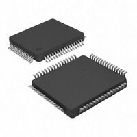
KSZ8873MLL AM Micrel Inc, KSZ8873MLL AM Datasheet - Page 33

KSZ8873MLL AM
Manufacturer Part Number
KSZ8873MLL AM
Description
IC ETHERNET SWITCH 3PORT 64-LQFP
Manufacturer
Micrel Inc
Specifications of KSZ8873MLL AM
Controller Type
Ethernet Switch Controller
Interface
MII
Voltage - Supply
1.8V, 2.5V, 3.3V
Operating Temperature
-40°C ~ 85°C
Mounting Type
Surface Mount
Package / Case
64-LQFP
Lead Free Status / RoHS Status
Lead free / RoHS Compliant
Current - Supply
-
Lead Free Status / RoHS Status
Not Compliant, Lead free / RoHS Compliant
Other names
576-3633
KSZ8873MLL AM
KSZ8873MLLAM
KSZ8873MLL AM
KSZ8873MLLAM
Micrel, Inc.
QoS Priority Support
The KSZ8873MLL/FLL/RLL provides Quality of Service (QoS) for applications such as VoIP and video conferencing.
Offering four priority queues per port, the per-port transmit queue can be split into four priority queues: Queue 3 is the
highest priority queue and Queue 0 is the lowest priority queue. Bit [0] of registers 16, 32 and 48 is used to enable split
transmit queues for ports 1, 2 and 3, respectively. If a port's transmit queue is not split, high priority and low priority
packets have equal priority in the transmit queue.
There is an additional option to either always deliver high priority packets first or use weighted fair queuing for the four
priority queues. This global option is set and explained in bit [3] of register 5.
Port-Based Priority
With port-based priority, each ingress port is individually classified as a high priority receiving port. All packets received at
the high priority receiving port are marked as high priority and are sent to the high-priority transmit queue if the
corresponding transmit queue is split. Bits [4:3] of registers 16, 32 and 48 are used to enable port-based priority for ports
1, 2 and 3, respectively.
802.1p-Based Priority
For 802.1p-based priority, the KSZ8873MLL/FLL/RLL examines the ingress (incoming) packets to determine whether they
are tagged. If tagged, the 3-bit priority field in the VLAN tag is retrieved and compared against the “priority mapping” value,
as specified by the registers 12 and 13. The “priority mapping” value is programmable.
The following figure illustrates how the 802.1p priority field is embedded in the 802.1Q VLAN tag.
802.1p-based priority is enabled by bit [5] of registers 16, 32 and 48 for ports 1, 2 and 3, respectively.
The KSZ8873MLL/FLL/RLL provides the option to insert or remove the priority tagged frame's header at each individual
egress port. This header, consisting of the 2 bytes VLAN Protocol ID (VPID) and the 2-byte Tag Control Information field
(TCI), is also referred to as the IEEE 802.1Q VLAN tag.
Tag Insertion is enabled by bit [2] of registers 16, 32 and 48 for ports 1, 2 and 3, respectively. At the egress port,
untagged packets are tagged with the ingress port’s default tag. The default tags are programmed in register sets {19,20},
{35,36} and {51,52} for ports 1, 2 and 3, respectively and the source port VID has to be inserted at selected egress ports
by bit[5:0] of register 194. The KSZ8873MLL/FLL/RLL will not add tags to already tagged packets.
Tag Removal is enabled by bit [1] of registers 16, 32 and 48 for ports 1, 2 and 3, respectively. At the egress port, tagged
packets will have their 802.1Q VLAN Tags removed. The KSZ8873MLL/FLL/RLL will not modify untagged packets.
The CRC is recalculated for both tag insertion and tag removal.
802.1p Priority Field Re-mapping is a QoS feature that allows the KSZ8873MLL/FLL/RLL to set the “User Priority
Ceiling” at any ingress port. If the ingress packet’s priority field has a higher priority value than the default tag’s priority
field of the ingress port, the packet’s priority field is replaced with the default tag’s priority field.
September 2009
Bytes
802.1q VLAN Tag
Preamble
8
Bits
DA
6
Tagged Packet Type
(8100 for Ethernet)
16
Figure 6. 802.1p Priority Field Format
SA
6
VPID
2
802.1p
TCI
2
3
1
33
length
2
VLAN ID
12
LLC
46-1500
Data
KSZ8873MLL/FLL/RLL
FCS
M9999-092309-1.2
4


