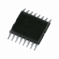
SC18IM700IPW,112 NXP Semiconductors, SC18IM700IPW,112 Datasheet - Page 7

SC18IM700IPW,112
Manufacturer Part Number
SC18IM700IPW,112
Description
IC CTRL I2C W/UART 16-TSSOP
Manufacturer
NXP Semiconductors
Type
Master I2C bus controller with UART interfacer
Datasheet
1.SC18IM700IPW128.pdf
(22 pages)
Specifications of SC18IM700IPW,112
Package / Case
16-TSSOP
Controller Type
I²C Bus Controller
Interface
I²C, UART
Voltage - Supply
2.4 V ~ 3.6 V
Current - Supply
9mA
Operating Temperature
-40°C ~ 85°C
Mounting Type
Surface Mount
Data Rate
9600 bit/s
Supply Voltage (max)
+ 5.5 V
Supply Voltage (min)
- 0.5 V
Supply Current
15 mA
Maximum Operating Temperature
+ 125 C
Minimum Operating Temperature
- 55 C
Mounting Style
SMD/SMT
Operating Supply Voltage
2.3 V to 3.6 V
Lead Free Status / RoHS Status
Lead free / RoHS Compliant
For Use With
568-3512 - DEMO BOARD UART TO I2C
Lead Free Status / Rohs Status
Lead free / RoHS Compliant
Other names
568-3231-5
935280629112
SC18IM700IPW
935280629112
SC18IM700IPW
Available stocks
Company
Part Number
Manufacturer
Quantity
Price
Company:
Part Number:
SC18IM700IPW,112
Manufacturer:
Renesas
Quantity:
51
NXP Semiconductors
SC18IM700_2
Product data sheet
7.1.8 Repeated START: write after write
7.1.9 Power-down mode
The SC18IM700 also supports ‘write after write’ command as specified in the NXP
Semiconductors I
write command without having to issue a STOP condition between the two commands.
The host issues a write command as normal, then immediately issues a second write
command without sending a STOP (P) character after the first write command.
The SC18IM700 can be placed in a low-power mode. In this mode the internal oscillator is
stopped and SC18IM700 will no longer respond to the host messages. Enter the
Power-down mode by sending the power-down character Z (0x5A) followed by the two
defined bytes, which are 0x5A and followed by 0xA5. If the exact message is not received,
the device will not enter the power-down state.
Upon entering the power-down state, SC18IM700 places the WAKEUP pin in a HIGH
state. To have the device leave the power-down state, the WAKEUP pin should be brought
LOW. A 1 k resistor must be connected between the WAKEUP pin and V
Fig 9. Repeated START: read after write
Fig 10. Repeated START: write after write
Fig 11. Power-down mode
S CHAR.
DATA N
2
SLAVE ADR.
18IM responds
C-bus specification. This allows a write command to be sent after a
S CHAR.
DATA 0
+ W
Rev. 02 — 10 August 2007
S CHAR.
DATA N
SLAVE ADR.
Z CHAR.
SLAVE ADR. + W
OF BYTES
+ W
NUMBER
S CHAR.
DATA N
0x5A
SLAVE ADR. + R
Master I
OF BYTES
NUMBER
DATA 0
OF BYTES
NUMBER
0xA5
2
C-bus controller with UART interface
DATA 0
OF BYTES
NUMBER
P CHAR.
002aac056
DATA 0
P CHAR.
002aac054
SC18IM700
DATA N
© NXP B.V. 2007. All rights reserved.
DD
P CHAR.
002aac055
.
7 of 22


