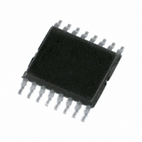
SC18IM700IPW,112 NXP Semiconductors, SC18IM700IPW,112 Datasheet - Page 15

SC18IM700IPW,112
Manufacturer Part Number
SC18IM700IPW,112
Description
IC CTRL I2C W/UART 16-TSSOP
Manufacturer
NXP Semiconductors
Type
Master I2C bus controller with UART interfacer
Datasheet
1.SC18IM700IPW128.pdf
(22 pages)
Specifications of SC18IM700IPW,112
Package / Case
16-TSSOP
Controller Type
I²C Bus Controller
Interface
I²C, UART
Voltage - Supply
2.4 V ~ 3.6 V
Current - Supply
9mA
Operating Temperature
-40°C ~ 85°C
Mounting Type
Surface Mount
Data Rate
9600 bit/s
Supply Voltage (max)
+ 5.5 V
Supply Voltage (min)
- 0.5 V
Supply Current
15 mA
Maximum Operating Temperature
+ 125 C
Minimum Operating Temperature
- 55 C
Mounting Style
SMD/SMT
Operating Supply Voltage
2.3 V to 3.6 V
Lead Free Status / RoHS Status
Lead free / RoHS Compliant
For Use With
568-3512 - DEMO BOARD UART TO I2C
Lead Free Status / Rohs Status
Lead free / RoHS Compliant
Other names
568-3231-5
935280629112
SC18IM700IPW
935280629112
SC18IM700IPW
Available stocks
Company
Part Number
Manufacturer
Quantity
Price
Company:
Part Number:
SC18IM700IPW,112
Manufacturer:
Renesas
Quantity:
51
NXP Semiconductors
11. Static characteristics
Table 11.
V
[1]
[2]
[3]
[4]
[5]
[6]
[7]
SC18IM700_2
Product data sheet
Symbol
I
V
V
V
V
V
V
V
C
I
I
I
R
DD
IL
LI
T(HL)
DD
POR
th(HL)
IL
th(LH)
IH
OL
OH
io
RESET_N(int)
= 2.4 V to 3.6 V; T
Typical ratings are not guaranteed. The values listed are at room temperature, 3 V.
See
exceed the related specification.
Pin capacitance is characterized but not tested.
Measured with GPIO in quasi-bidirectional mode.
Measured with GPIO in high-impedance mode.
GPIO in quasi-bidirectional mode with weak pull-up (applies to all GPIO pins with pull-ups). Does not apply to open-drain pins.
GPIO pins source a transition current when used in quasi-bidirectional mode and externally driven from logic 1 to logic 0. This current is
highest when V
Table 10 “Limiting values”
Static characteristics
Parameter
supply current
power-on reset voltage
negative-going threshold
voltage
LOW-level input voltage
positive-going threshold
voltage
HIGH-level input voltage SCL, SDA only
LOW-level output
voltage
HIGH-level output
voltage
input/output capacitance
LOW-level input current
input leakage current
negative-going transition
current
internal pull-up
resistance on pin
RESET
I
is approximately 2 V.
amb
= 40 C to +85 C; unless otherwise specified.
for steady state (non-transient) limits on I
Conditions
V
except SCL, SDA
SCL, SDA only
except SCL, SDA
I
I
I
GPIO3 to GPIO7
I
GPIO0 to GPIO2
I
mode; all GPIOs
logic 0; all ports; V
all ports; V
logic 1-to-0; all ports; V
V
OL
OL
OH
OH
OH
DD
DD
Operating mode; f = 7.3728 MHz
Idle mode; f = 7.3728 MHz
Power-down mode (sleep);
GPIO0 to GPIO7 as inputs;
inputs at V
= 20 mA
= 3.2 mA
= 20 mA; Push-pull mode;
= 3.2 mA; Push-pull mode;
= 20 mA; quasi-bidirectional
= 3.6 V
= 3.6 V
Rev. 02 — 10 August 2007
I
= V
DD
IL
or V
I
= 0.4 V
IH
I
= 2.0 V at
OL
Master I
or I
OH
. If I
OL
2
[6][7]
C-bus controller with UART interface
/I
[2]
[2]
[3]
[4]
[5]
OH
Min
-
-
-
-
0.22V
-
0.7V
-
-
0.8V
V
V
-
-
-
10
exceeds the test condition, V
0.5
30
DD
DD
DD
DD
DD
0.7 V
0.3 V
Typ
9
3.25
50
-
0.4V
-
0.6V
-
0.6
0.2
-
-
-
-
-
-
SC18IM700
DD
DD
[1]
DD
DD
0.4 -
0.2 -
© NXP B.V. 2007. All rights reserved.
Max
15
5
70
0.2
-
0.3V
0.7V
5.5
1.0
0.3
-
15
30
80
10
450
OL
DD
DD
/V
OH
15 of 22
may
Unit
mA
mA
V
V
V
V
V
V
V
V
V
V
pF
k
A
A
A
A


