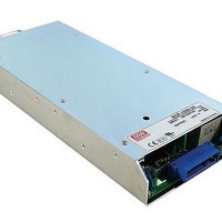
RCP-1000-12 Mean Well, RCP-1000-12 Datasheet - Page 5

RCP-1000-12
Manufacturer Part Number
RCP-1000-12
Description
Linear & Switching Power Supplies 720W 12V 60A W/PFC
Manufacturer
Mean Well
Datasheet
1.RCP-1000-24.pdf
(8 pages)
Specifications of RCP-1000-12
Lead Free Status / Rohs Status
Lead free / RoHS Compliant
CN500 Pin No. Assignment
CN500 IN/OUT Connector pins function description
Derating Curve
Connector Pin No. Assignment(CN500) : D-Type Right Angle 25 positions
Pin No. Function Description
3,10,17
4,11,18
5,12,19
Pin No.
1,8,15
2,9,16
14
20
21
22
23
24
25
1
2
3
4
5
6
7
100
80
60
40
20
-20
T-ALARM
GND-AUX
ON/OFF
+5V-AUX
V-TRIM
Assignment
T-ALARM-A
AC-OK
DC-OK
ON/OFF-A
V-TRIM-A
AC-OK-A
DC-OK-A
SCL
SDA
CS
+S
+V
-S
-V
0
1000 ~ 3000W Front End Power System
AMBIENT TEMPERATURE ( )
Each unit can separately turn the output on and off by electrical or dry contact between ON/OFF A,B,C(pin 1,8,15) and -S(pin 21). Short: ON, Open:OFF.
Low : When the input voltage is
High : When the Vout 80%+/-5%. Low : When Vout
Connection for output voltage trimming. The voltage can be trimmed within its defined range.
High : When the internal temperature is within safe limit. Low : 10
Auxiliary voltage output, 4.3~5.3V, referenced to GND-AUX(pin 7). The maximum load current is 0.3A. This output has the built-in
"Oring diodes" and is not controlled by the remote ON/OFF control.
Auxiliary voltage output GND. The signal return is isolated from the output terminals (+V & -V).
Current sharing signal. When units are connected in parallel, the CS pins of the units should be connected to allow current balance
between units.
Positive sensing. The +S signal should be connected to the positive terminal of the load. The +S and -S leads should be twisted in pair to
minimize noise pick-up effect. The maximum line drop compensation is 0.5V.
Negative sensing. The -S signal should be connected to the negative terminal of the load. The -S and +S leads should be twisted in pair to
minimize noise pick-up effect. The maximum line drop compensation is 0.5V.
Positive output voltage. For local sense use only, can't be connected directly to the load.
Serial clock used in the I C interface option. Refer to the I C interface description.
Serial data used in the I C interface option. Refer to the I C interface description.
Negative output voltage. For local sense use only, can't be connected directly to the load.
10
Pin No.
10
6
7
8
9
20
30
Assignment
ON/OFF-B
GND-AUX
DC-OK-B
+5V-AUX
AC-OK-B
40
50
82Vrms +/-4V. High : when the input voltage in 82Vrms +/-4V.
Pin No.
12
13
14
15
11
60
70
T-ALARM-B
Assignment
V-TRIM-B
ON/OFF-C
NC
CS
80%+/-5%
Static Characteristics
Pin No.
below the thermal shut down limit.
100
16
17
18
19
20
90
80
70
60
50
40
90
Assignment
T-ALARM-C
V-TRIM-C
AC-OK-C
DC-OK-C
95
+S
INPUT VOLTAGE (VAC) 60Hz
100
Pin No.
21
22
23
24
25
115
Assignment
SDA
SCL
+V
-S
-V
File Name:RCP series-SPEC 2010-10-18
R C P
Ta=25
264
s e r i e s


